EAV - EME/EMD Rev. A Models
R G CY C R W C R W C R W C R W C R WO
------------ ZONE 1 ------------ ---- ZONE 2 ---- ---- ZONE 3 ---- ---- ZONE 4 ---- ---- ZONE 5 ---- ---- ZONE 6 ----
R Y G
FAN COIL
OC O Y1C Y1
WV HEAT PUMP
FAN COIL
ZONE VALVE
RELAY
FAN COIL/
RADIANT RELAY
TRANSFORMER A
FAN COIL
ISOLATION
RELAY 1
FAN COIL
ISOLATION
RELAY 2
COILCOIL
COIL
COIL
COIL
COM
COMCOM
NC
NO
NC
NC NC
NO
NC
NO
NO NO
FAN COIL/
RADIANT RELAY
TRANSFORMER B
COIL
COM
NC
NO
NO
NC
HEAT/COOL
RELAY
C
NO
NC
NC
NO
Y2C Y2
COIL
COM
1 2
Expansion
HI TEMP
RELAY
A**
A**
B**
B**
1 2 3 4
ZONE 1
1 2 3 4
ZONE 2
1 2 3 4
ZONE 3
1 2 3 4
ZONE 4
1 2 3 4
ZONE 5
1 2 3 4
ZONE 6
2 WIRE ZONE VALVE
(NO END SWITCH)
MUST USE JUMPER
TACO
3 WIRE
ZONE VALVE
1
2
3
JUMPER
3 & 4
MOTOR END
SWITCH
4 WIRE ZONE VALVE
(POWER OPEN,
SELF CLOSING)
ZVC 406 – 4
ZONE VALVE CONTROL
N/O
COM
N/C
PUMP END
SWITCH
ZONE 6 PUMP
END SWITCH
24 VAC ZONE VALVES PRIORITY
X X
Powered from Transformer A Powered from Transformer B
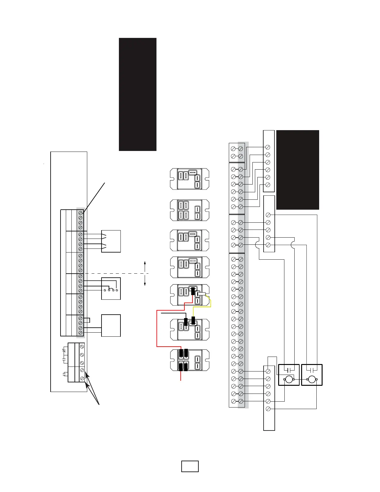
Wiring from this terminal strip to the relays and Taco zone controller not shown in this diagram.
Thermostat wiring**
Field wiring is shown
as gray shaded areas
(high voltage wiring
not shown)
4
Use these terminals
to enable system
pump (see piping
diagrams).*
*These contacts will close with a call from
any thermostat. For constant speed pump,
use these contacts to power the pump
when there is a htg/clg call (break the “L”
terminal for a 115V pump). For variable
speed pump, use these contacts to enable
the pump (typically a contact closure will
“tell” the pump to start modulating).
R G CYO
W
C WGY
R
Dual Fuel
Heat Pump
Thermostat
Furnace
**This panel is wired from the factory as a cooling only fan coil for zone 1. If heating and cooling is desired for the zone 1 A-coil, make
the following changes:
1. Remove the two red wires labeled A at the rst relay on the left. Using a quick-connect junction, plug the two red wires together.
2. Remove the black wire and the yellow wire from the second relay from the left (labeled B). Using a quick-connect junction, plug
the two wires (one black and one yellow) together.
Secon 8: Field Wiring
Diagram HTGCLG-3:
Heang/Cooling A-Coil
with Fossil Furnace Backup
(A-Coil Cooling or Heang &
Cooling) Up to 5 Radiant
Heang Zones
⚠ CAUTION ⚠
A-COIL MUST BE 2 TONS OR LARGER FOR THIS
APPLICATION. IF A-COIL IS SMALLER THAN 2
TONS, A BUFFER TANK IS REQUIRED (USE
DIAGRAM HTGCLG-7 AND FIGURE 16C).
HHEATHEAT
COOL
EM
indoor
Module
7 8 9 1011 12
⚠NOTICE ⚠
THE EM UNIT TERMINALS ARE
POLARITY SENSITIVE. TERMINALS
7,9, & 11 ARE COMMON. ENSURE
THAT OC, Y1C, AND Y2C ARE
CONNECTED TO COMMON.