Enertech Global
EAV - EME/EMD Rev. A Models
Installaon and Operaons Manual
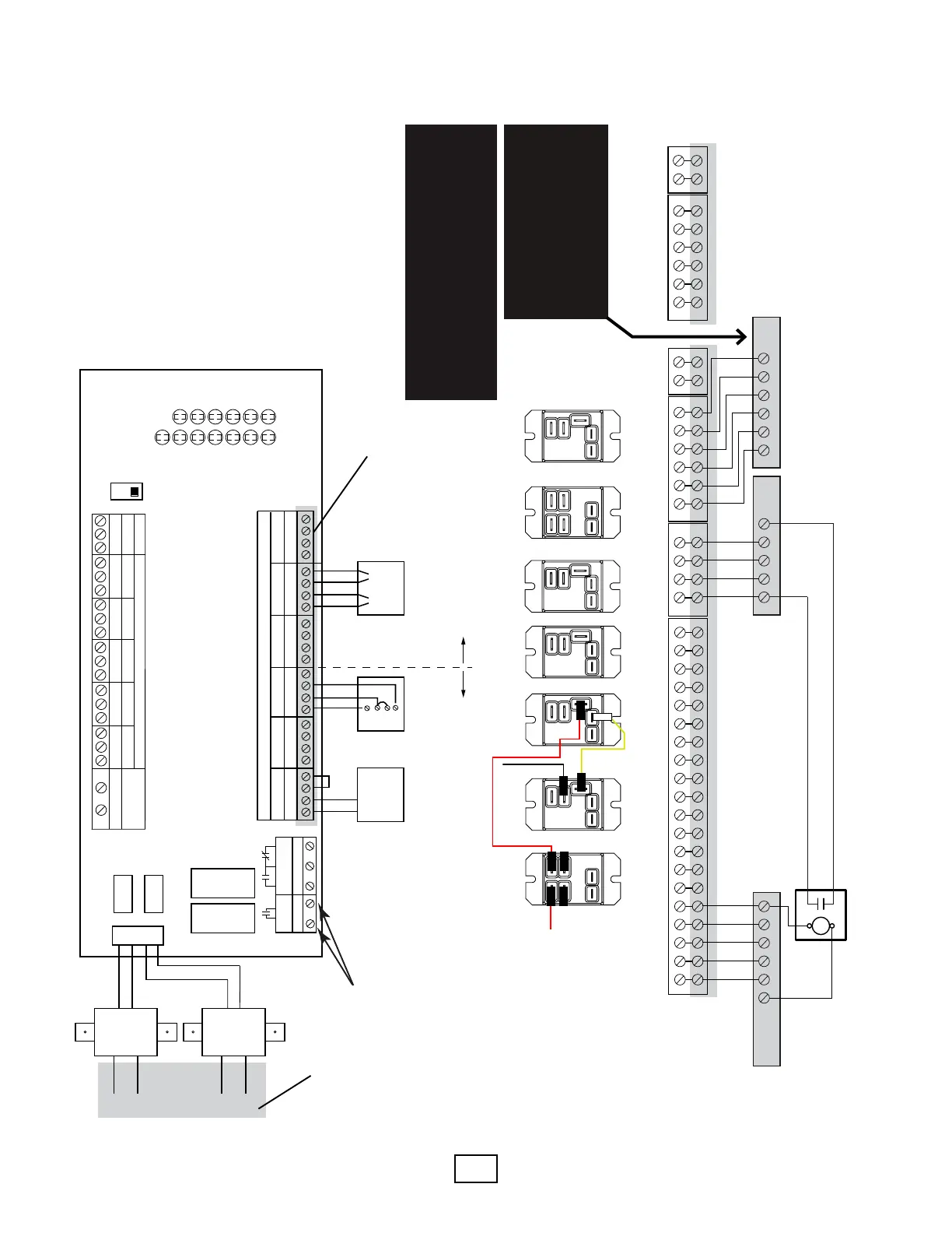
**This panel is wired from the factory as a cooling only fan coil for zone 1. If heating and cooling is desired for the zone 1 fan coil, make the following changes:
1. Remove the two red wires labeled A at the rst relay on the left. Using a quick-connect junction, plug the two red wires together.
2. Remove the black wire and the yellow wire from the second relay from the left (labeled B). Using a quick-connect junction, plug the two wires (one black and one yellow) together.
R G CY C R W C R W C R W C R W C R WO
------------ ZONE 1 ------------ ---- ZONE 2 ---- ---- ZONE 3 ---- ---- ZONE 4 ---- ---- ZONE 5 ---- ---- ZONE 6 ----
R Y G
FAN COIL
OC O Y1C Y1
WV HEAT PUMP
FAN COIL
ZONE VALVE
RELAY
FAN COIL/
RADIANT RELAY
TRANSFORMER A
FAN COIL
ISOLATION
RELAY 1
FAN COIL
ISOLATION
RELAY 2
COILCOIL
COIL
COIL
COIL
COM
COMCOM
NC
NO
NC
NC NC
NO
NC
NO
NO NO
FAN COIL/
RADIANT RELAY
TRANSFORMER B
COIL
COM
NC
NO
NO
NC
HEAT/COOL
RELAY
C
NO
NC
NC
NO
Y2C Y2
COIL
COM
1 2
Expansion
HI TEMP
RELAY
A**
A**
B**
B**
1 2 3 4
ZONE 1
1 2 3 4
ZONE 2
1 2 3 4
ZONE 3
1 2 3 4
ZONE 4
1 2 3 4
ZONE 5
1 2 3 4
ZONE 6
2 WIRE ZONE VALVE
(NO END SWITCH)
MUST USE JUMPER
TACO
3 WIRE
ZONE VALVE
1
2
3
JUMPER
3 & 4
MOTOR END
SWITCH
4 WIRE ZONE VALVE
(POWER OPEN,
SELF CLOSING)
ZVC 406 – 4
SIX ZONE
ZONE VALVE CONTROL
24 VAC
FACTORY
INSTALLED
TRANSFORMER
120 VAC
INPUT
WHITE
BLACK
POWER IN
24 VAC
24 VAC
FACTORY
INSTALLED
TRANSFORMER
120 VAC
INPUT
WHITE
BLACK
N/O
COM
N/C
PUMP END
SWITCH
ZONE 6 PUMP
END SWITCH
T STAT 1
VALVE 1
T STAT 2
VALVE 2
T STAT 3
VALVE 3
T STAT 4
VALVE 4
VALVE 5
T STAT 6
VALVE 6
POWER
LED
INDICATORS
T STAT 5
ZONE 1 ZONE 2 ZONE 3 ZONE 4 ZONE 5 ZONE 6
ISOLATED
X X
END SWITCH THERMOSTATS (24 VAC) PRIORITY
24 VAC ZONE VALVES PRIORITY
X X
ZONE 6
PRIORITY
OFF
ON
FUSE
5 AMP
R W
R W R W R WC C C
R W C
C
FUSE
5 AMP
R W
C
A
B
Powered from Transformer A Powered from Transformer B
Wiring from this terminal strip to the relays and Taco zone controller not shown in this diagram.
Thermostats are factory wired from the Taco zone board to the terminals at the bottom of the page.
Thermostat wiring**
Field wiring is shown
as gray shaded areas
OC O Y1C Y1 Y2C Y2 1 2
Expansion Module Connections***
***Expansion module provides an additional
fan coil zone and an addtiional 5 radiant
zones. Connect terminals from main
module to the same terminals in the
expansion module. If main module has
been modied to allow heating and
cooling in zone 1, the expansion module
must also be modied.
R G CY1O
W
C WGY1
R
Heat Pump
Thermostat
Fan Coil
Optional eld
installed relay
if fan coil will
have backup
electric heat
3
4
Use these terminals
to enable system
pump (see piping
diagrams).*
*These contacts will close with a call from
any thermostat. For constant speed pump,
use these contacts to power the pump
when there is a htg/clg call (break the “L”
terminal for a 115V pump). For variable
speed pump, use these contacts to enable
the pump (typically a contact closure will
“tell” the pump to start modulating).
Field wiring is shown
as gray shaded areas
Secon 8: Field Wiring
Diagram HTGCLG-1:
Heang/Cooling
One Fan Coil (Cooling or
Heang & Cooling)
Up to 5 Radiant Heang
Zones***
⚠ CAUTION ⚠
ALL FAN COILS MUST BE 2 TONS OR LARGER FOR
THIS APPLICATION. IF ANY FAN COIL IS SMALLER
THAN 2 TONS, A BUFFER TANK IS REQUIRED
(USE DIAGRAM HTGCLG-7 AND FIGURE 16C).
HHEATHEAT
COOL
EM
indoor
Module
⚠NOTICE ⚠
THE EM UNIT TERMINALS ARE
POLARITY SENSITIVE. TERMINALS
7,9, & 11 ARE COMMON. ENSURE
THAT OC, Y1C, AND Y2C ARE
CONNECTED TO COMMON.