Installation Installation and Operation Manual - COMTEC
®
6000
10 Doc.-ID: COM6000_11022020_EN
2.2 Installation of probe signal cable FEP-0007/8
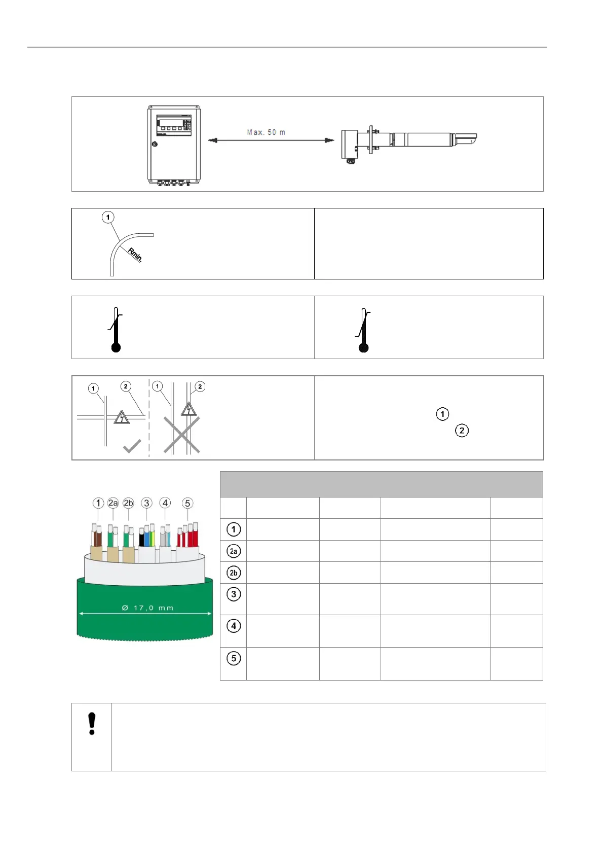
Abide by the maximum cable length (max. 50m)
Note the minimum bending radius.
FEP-0007Rmin=252 mm
FEP-0008 Rmin=329 mm
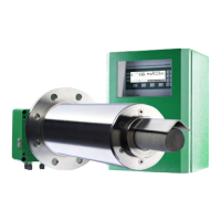
Temperature during installa-
tion
Temperature during operation
Cross the probe signal cable (FEP-0007/8) at right
angle to any power supply cables .
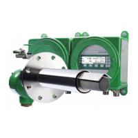
COMTEC Probe Cable FEP-0007 (FEP-0008 armored)
No. Function Diameter Colors Info.
Measuring cell 2 x 0,75 mm
2
white-brown / brown With shield
Thermocouple 1 2 x 0,75 mm
2
green / white With shield
Thermocouple 2 2 x 0,75 mm
2
green / white With shield
Probe heater 3 x 1,5 mm
2
black / blue / green-
yellow
Probe Solenoid
valve
2 x 0,75mm
2
grey / grey-blue
CO
e
Sensor
heater and
4 x 1,0mm
2
red-white / red-white /
red / red
Figure 5 - Probe cable FEP-0007
Caution
Only use ENOTEC probe cables, as the thermocouple cables 2a and 2b are compensating cables and
are necessary for correct measurement.
The shield of the probe cable must only be connected at the electronic housing at the PE terminal. Under
no circumstance should the shield also be connected at the probe.
5 °C
Min.
+50 °C
Max.
-40 °C
Min.
+90 °C
Max.