Installation and Operation Manual - COMTEC
®
6000 Installation
Doc.-ID: COM6000_11022020_EN 15
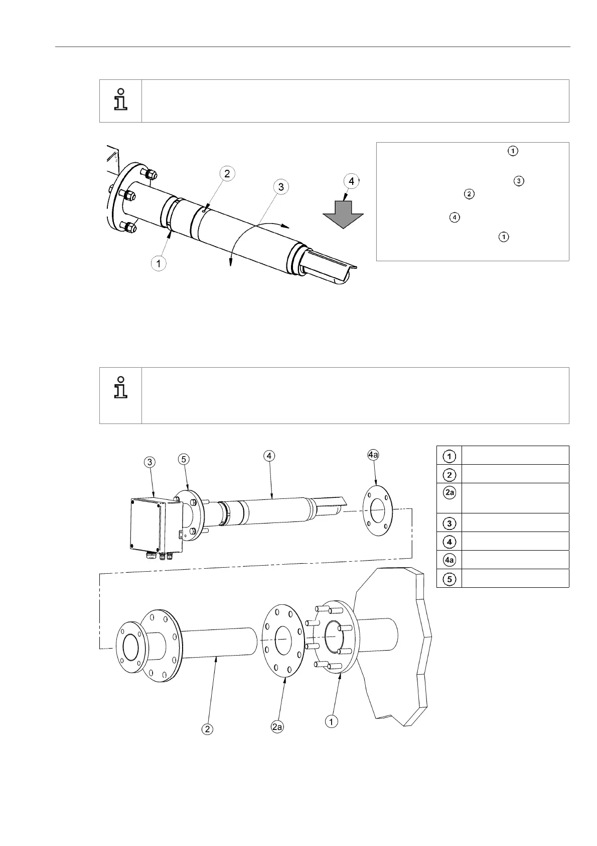
2.9 Adjustment of the Probe Filter Head
Info
Determine the flow direction of the process gas at the place of installation.
Unscrew the retaining ring (clock-
wise) with a hook wrench
Turn the filter head V-shield into the
correct position with a pin wrench.
The V-shield must face the direction of
the flue gas .
Tighten the retainer ring after adjust-
ing the filter head.
Figure 9 - Adjustment of the V-Shield
2.10 Probe Protection Tube at the Mounting Flange
Info
Use only new and undamaged gaskets for the installation of the probe. Tighten the nuts firmly, to guaran-
tee the gastight seal of the flange connection. Never leave the probe unheated for longer periods of time
in the running process.
Counter flange
Protection tube
Protection tube flange
gasket
Connection box
O
2
/CO
e
probe
Probe flange gasket
Probe flange
Figure 10 - Mounting of the protection tube at the mounting flange