Installation and Operation Manual - COMTEC
®
6000 Installation
Doc.-ID: COM6000_11022020_EN 17
2.12 Electrical Connections of the Probe
Info
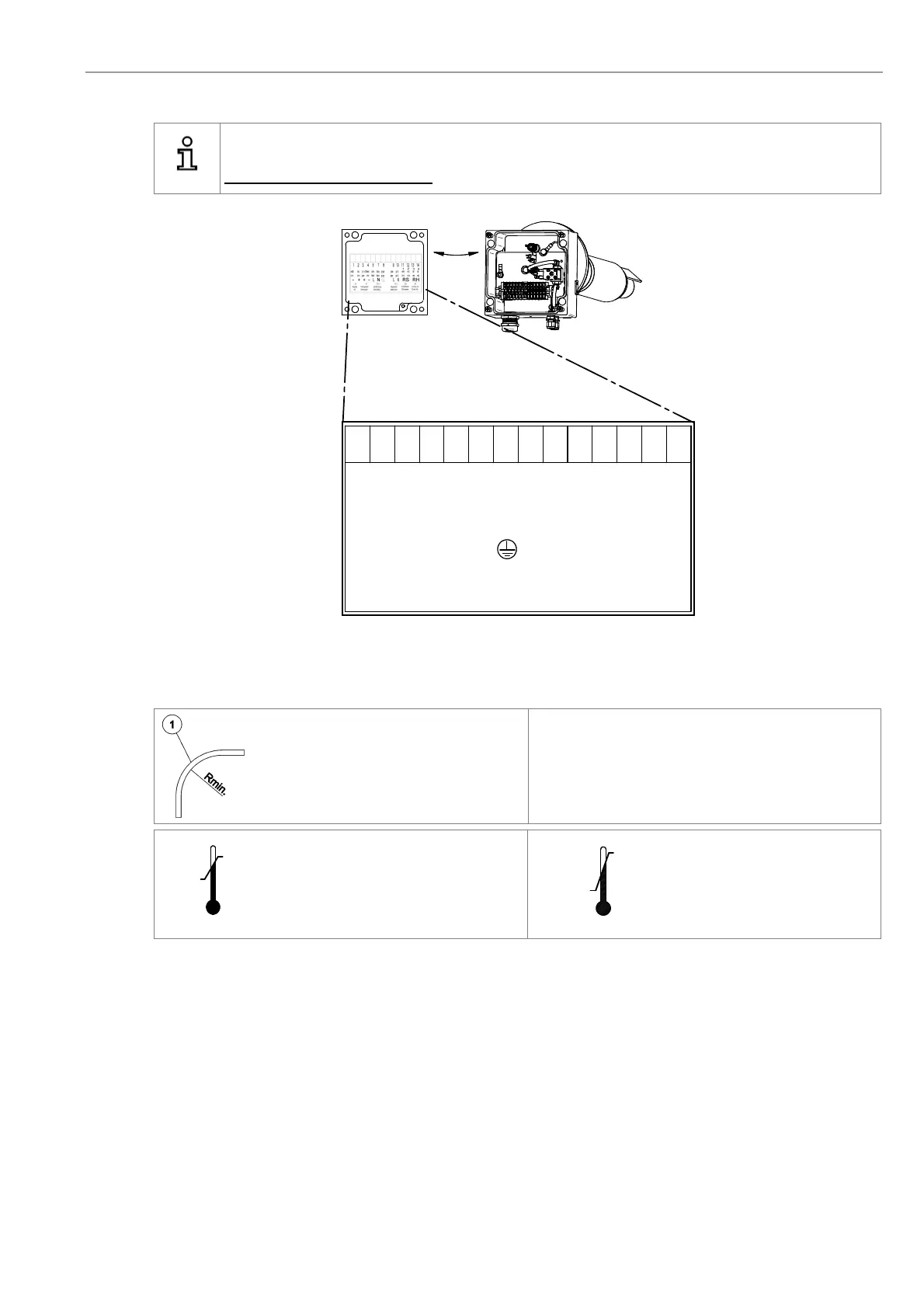
The Probe Signal Cable FEP-0007/8 has to be connected to the terminal board in the probe terminal box.
Do not connect the shield here.
Figure 12 - Electrical connections of the probe connection box
2.13 Requirements for Pneumatic Cable FEP-0002
Note the minimum bending radius.
FEP-0002R
min
= 138 mm
Temp. during installation
Temp. during operation
1234 6 8
cell thermocouple probe heating
SondenheizungThermoelement
mV
mV
115 V ~
blue
7
blau
gr.ye.
gr.ge.schw.
black
-
+
braun
brown
grün
green
+
white
-
ws/br
wh/br
Messzelle
weiss
L
N
910
grau
grey
LN
115 V ~
Magnetventil
solenoid valve
11 12 13 14
1
2
3
4
RS RH
COe-Sensor
COe-sensor
0,5V 15V
gr.-bl.
gr.-bl.
COe-Sens. Heiz.
COe-sens. heat.
rot
red
rot
red
ws/rt
wh/rd
ws/rt
wh/rd
5 °C
Min.
+50 °C
Max.
-40 °C
Min.
+90 °C
Max.