Installation Installation and Operation Manual - COMTEC
®
6000
14 Doc.-ID: COM6000_11022020_EN
2.7 Installation of the probe
The flue gas temperature, pressure and all other process conditions must be in accordance with the specification.
Leave enough space for insertion/removal of the probe and protection tube (if supplied) and ensure access to the
measuring probe and/or connecting box.
Before cutting a hole in the flue gas duct, make sure that the inside of the duct has enough space for probe installa-
tion and that no soot is blown out nearby or any obstacles are in the way.
For probe lengths exceeding 2000 mm, a support must be mounted inside the duct (every 2 m) to prevent the probe
and mounting tube from flexing or bending. ENOTEC recommends installing the probe horizontally (- 1 ° to - 3 °)
for the fastest possible response time. A vertical (90 °) installation decreases the response time significant.
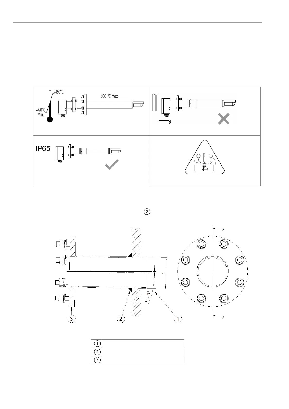
The ambient temperature at the connection box and
the process temperature must not be exceeded.
Avoid vibrations greater 2g
Maintain the protection class of the connection box. Heavy equipment, ensure proper lifting and carrying
2.8 Mounting of the Counter Flange at the Duct
The flange has to be mounted with an angle of 1° to 3° , so that condensed flue gas elements can flow back into
the duct.
Figure 8 - Mounting of the counter flange at the duct
Pitch of the counter flange
The flange has to be welded gastight.
Counter flange (supplied by customer)