Service and Maintenance Installation and Operation Manual - COMTEC
®
6000
42 Doc.-ID: COM6000_11022020_EN
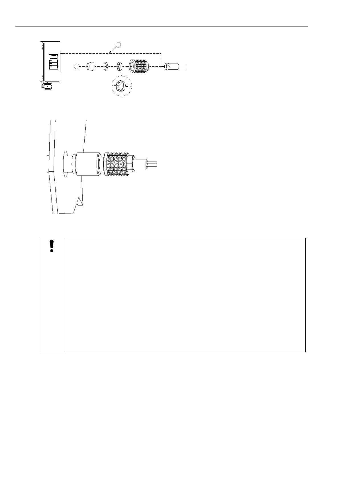
Prepare the new CO
e
sensor as follows:
Take the clamping ring, the O-ring, retainer
ring and the cap nut and cover them over
the CO
e
sensor.
Note: Mind the position of the bevel.
Bevel must face O-ring!
Figure 38 - Prepare the new COe sensor
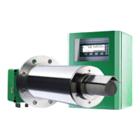
Insert the new CO
e
-sensor into the probe
Tighten the cap nut. Please tighten the cap
nut once more after the system and the
plant are in normal operation for two hours.
Connect the CO
e
sensor wires at the probe
terminal block no. 11-14.
Switch on the power supply
Figure 39 - Insert the new CO
e
sensor
Caution
The following parameters have to be entered to ensure correct measurement. Failure to observe this
information
willdestroytheCOesensorimmediately!
The CO
e
sensor must now be activated (via the software)
SYS-MENU System Configuration Set CO
e
measurement ON.
After a CO
e
sensor replacement, the following values need to be entered as specified in the test
certificate (see paragraph 4.2.17):
CO
e
RH
0
CO
e
Offset
CO
e
Alpha
CO
e
Beta
CO
e
Gamma
CO
e
Delta
CO
e
SO
2
correction value
If incorrect values have inadvertently been entered, switch the CO
e
measurement off and back on
again.
5.10.1 Seal the CO
e
sensor guide tube
In the event of the CO
e
sensor being removed for a prolonged period of time, the CO
e
sensor guide tube must be
sealed to avoid the intake of false air. This must be done with the locking rod and sealing kit for CO
e
sensors
which are delivered with the probe as accessories.
2
1