Installation and Operation Manual - COMTEC
®
6000 Service and Maintenance
Doc.-ID: COM6000_11022020_EN 39
5.8 Exchange of Probe Inner Part
Switch off the electronic unit, take the probe out of the protection tube and wait until it has cooled down.
Warning hot surface
The probe may only be removed with heat-insulated gloves. Before removing the probe, always switch off
the supply voltage to the electronic system. After removal, store the probe in a safe, protected place and
wait until it has cooled down below 35 °C/95 °F.
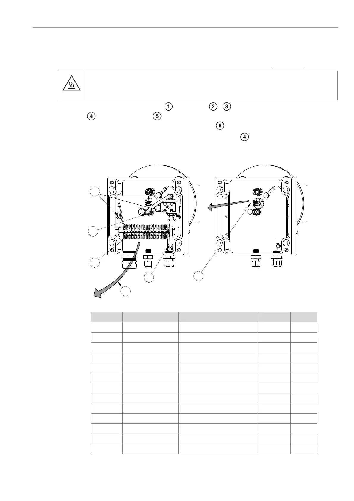
Disconnect the wires of the probe inner part , the two tubes - and the thin reference air tube. Loosen the
two screws and dismount the plate . Now the complete probe inner part (4 hole ceramic rod with measuring
signal wire, thermocouple and heater) can be unplugged carefully .
Move the new probe inner part carefully into the probe and screw the plate . The probe inner part is now pushed
against the cell by the spring. Connect all electrical and pneumatic connections. Connect the wires as follows
:
Figure 34 - Probe connection box
Terminal Color Description Polarity Unit
1 white/brown signal wire, measuring cell - mV
2 orange signal wire, measuring cell + mV
3 green thermocouple element 1 + mV
4 white thermocouple element 1 - mV
6 black heating element
7 blue heating element
8 green/yellow ground/earth heater
9 grey solenoid valve
10 grey / blue solenoid valve
11 white / red CO
e
sensor measuring value
12 white / red CO
e
sensor measuring value
13 red (no.3) CO
e
sensor heating element
14 red (no.4) CO
e
sensor heating element
1
4
2
3
5
6