Installation Installation and Operation Manual - COMTEC
®
6000
12 Doc.-ID: COM6000_11022020_EN
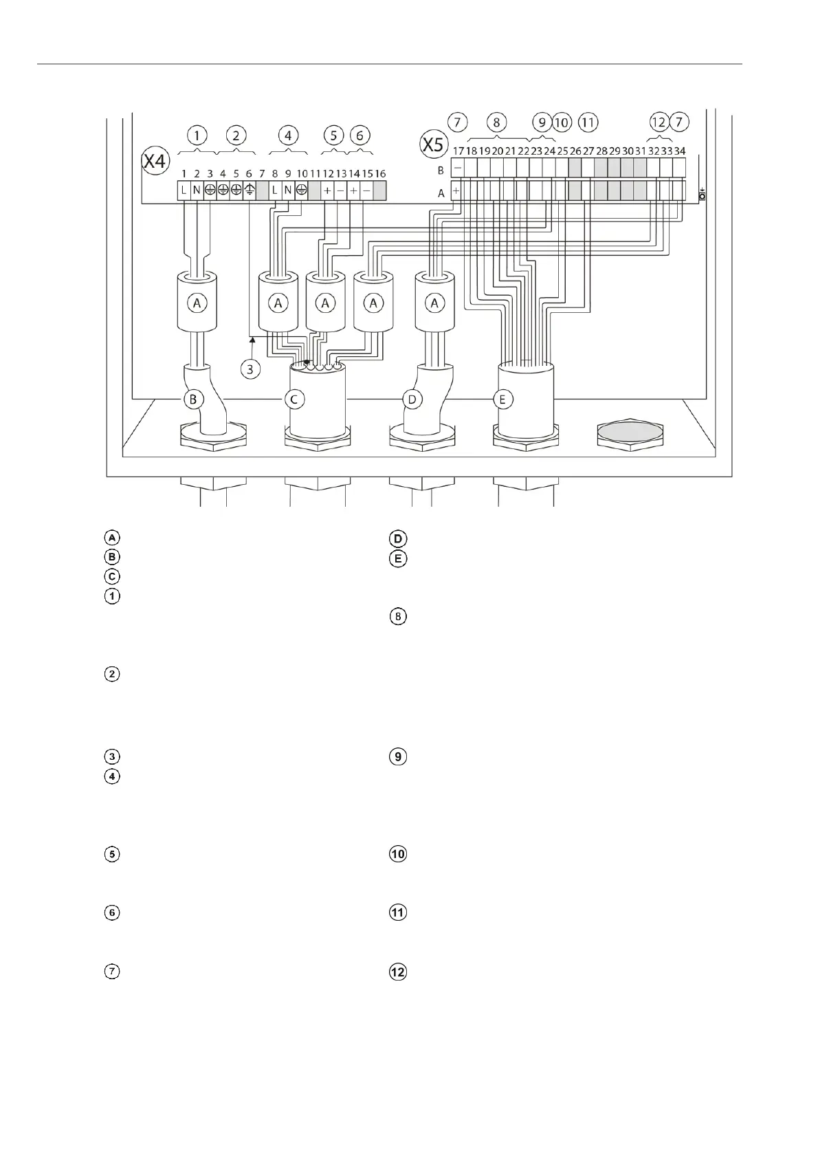
2.5 Wiring diagram of the Electronic Unit
Figure 6 - Wiring diagram of the electronic unit
Ferrite sleeves (Enclosed)
nalogue output cable (customer)
Power supply cable (customer) Status signal cable (customer)
Probe signal cable
Internal Power supply
1 L phase
Relay contacts for status signals -
Potential free
2 N neutral wire
3 PE protection earth 18 A/B Maintenance
Grounding
19 A/B System Error
4 PE protection earth 20 A/B Output A O
2
measuring range
5 PE protection earth 21 A/B Limit Alarm 1 (O
2
)
6 PE functional earth 22 A/B
Limit Alarm 2 (CO
e
)
Shielding Probe solenoid valve
Power supply probe heater (115V) 23 A
Internal Power supply for probe solenoid
valve (115VAC)
8 L black 23 B
9 N blue 24A L grey
10 PE green/yellow 24B N grey/blue
O
2
-sensor signal Measuring Range O
2
(12..24V DC- External supply)
12 + brown 25A +
13 - brown/white 25B -
Thermocouple (O
2
sensor) Calibration release (12..24V DC - External supply)
14 + green 27A +
15 - white 27B -
Analogue outputs (active 4-20mA)
CO
e
sensor
17A + O
2
32A
CO
e
sensor
white/red 2
17B - O
2
32B white/red 1
34A +
CO
e
33A
CO
e
sensor
red 4
34B
-
CO
e
33B red 3