Connecting AC and PoE Power
3-16 Hardware Installation
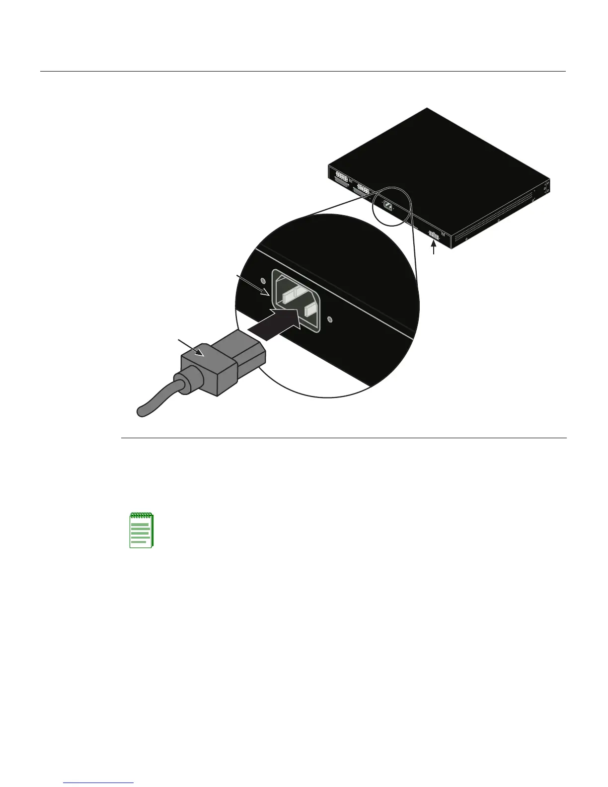
Figure 3-8 Connecting AC Power and RPS
3. ObservethepowerCPULED(notshown)locatedonthefrontpanel.Duringthe
initialization,theCPULEDwillstartbyilluminatingsolidamber,thenstartblinking
green,thenblinkingamber,thenblinkinggreenagainuntiltheendofthe
initialization,andthenturnssolidgreen.
Iftheswitchis
astandaloneunit,itwilltakeapp roximately30 secondsfortheswitch
tostartup.IftheswitchisastackManager,itcantakeupto3minutesormoretostart
up,dependingonthenumberofMemberswitchesinthestack.
1 AC power cord 2 AC power connector 3 Connector for external redundant power supply
Note: If the CPU LED illuminates solid red, there was a critical failure. For more
information about the LED indications and troubleshooting, refer to Chapter 4. If you need
additional help, contact Enterasys Networks. Refer to “Getting Help” on page xvi for
details.
R
e
d
u
n
d
a
n
t
P
o
w
e
r
S
u
p
p
l
y
A
C
L
IN
E
1
0
0
-
2
4
0
V
A
C
5
0
-
6
0
H
z
0
.
8
A
M
A
X
MAC ADDRES
S
SERI
AL
N
O.
S
T
A
C
K
U
P
S
T
A
C
K
D
O
W
N
À
Á
Â