13 GND O Ground
14 LED1 O LED drive signal (1)
15 LED8 O LED drive signal (8)
16 PSC O
17 SW6 I Panel switch input (6)
18 SW0 I Panel switch input (0)
19 SW4 I Panel switch input (4)
20 SW5 I Panel switch input (5)
21 SW1 I Panel switch input (1)
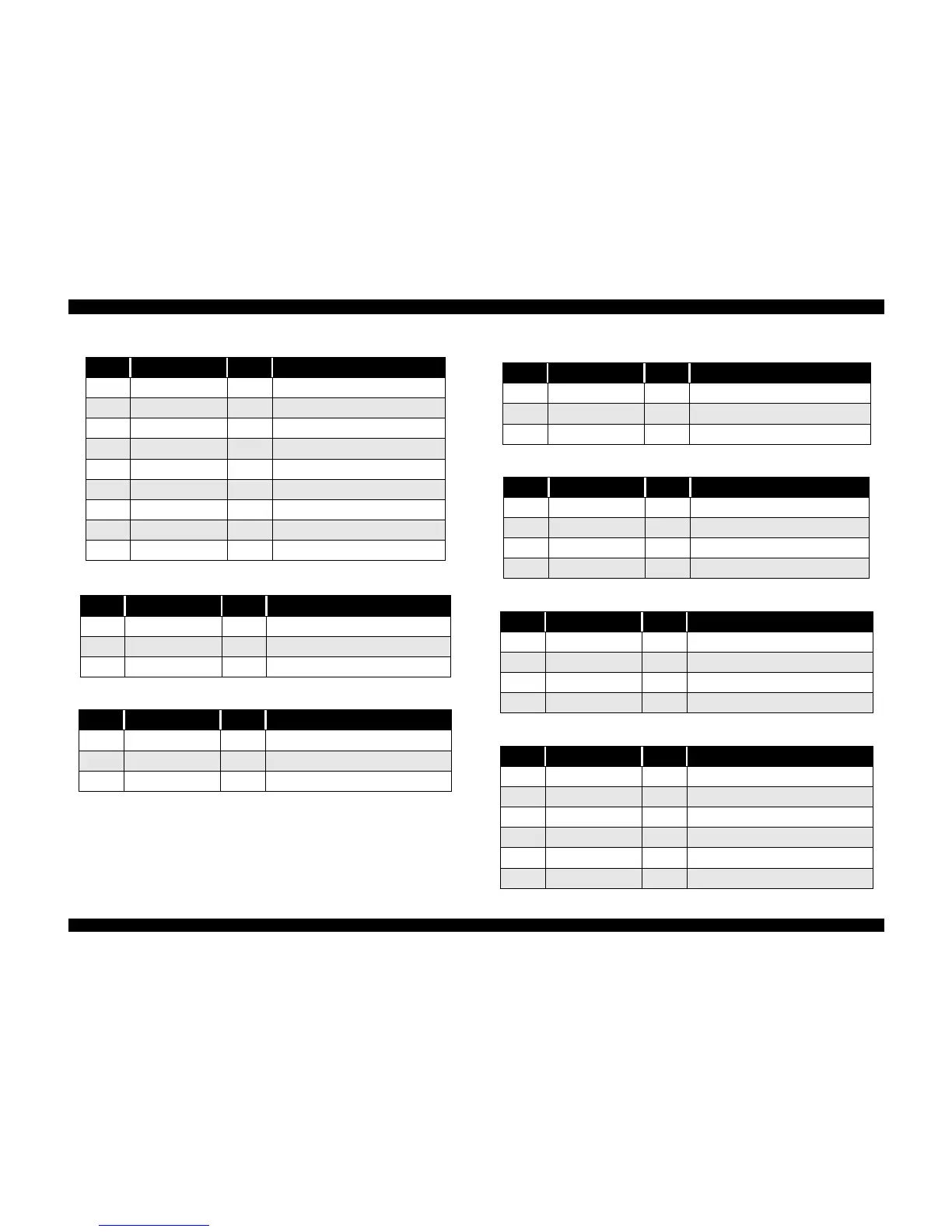
Table 7-3. Connector Pin Assignment-CN4
Pin No. Signal Name I/O Function
1 HP I Sensor detect signal
2 GND O Ground
3 HPV O Sensor power supply (+5V)
Table 7-4. Connector Pin Assignment-CN5
Pin No. Signal Name I/O Function
1 PE I Sensor detect signal
2 GND O Ground
3 PEV O Sensor power supply (+5V)
Table 7-2. Connector Pin Assignment-CN2
Pin No. Signal Name I/O Function
Table 7-5. Connector Pin Assignment-CN6
Pin No. Signal Name I/O Function
1 ASF I Sensor detect signal
2 GND O Ground
3 ASFV O Sensor power supply (+5V)
Table 7-6. Connector Pin Assignment-CN7
Pin No. Signal Name I/O Function
1 CR-A O Phase drive signal (A)
2 CR-B O Phase drive signal (B)
3 CR-/A O Phase drive signal (/A)
4 CR-/B O Phase drive signal (/B)
Table 7-7. Connector Pin Assignment-CN8
Pin No. Signal Name I/O Function
1 PF-A O Phase drive signal (A)
2 PF-B O Phase drive signal (B)
3 PF-/A O Phase drive signal (/A)
4 PF-/B O Phase drive signal (/B)
Table 7-8. Connector Pin Assignment-CN9
Pin No. Signal Name I/O Function
1 COB O
2 COC O
3 THM I Thermometer detect system
4 GND O Ground
5 LAT O Head data latch pulse output
6 GND O Ground
 Loading...