2.3.3 SCSI Interface
This scanner and the host are connected through USB I/F.
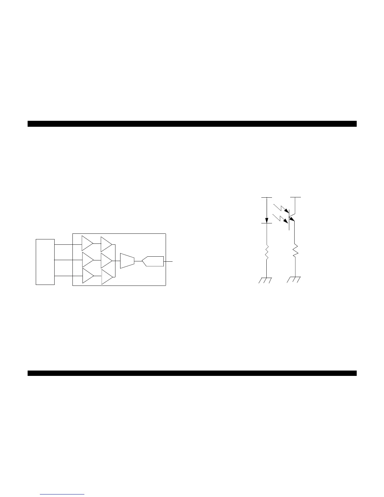
2.3.3.1 Video Circuit
The video circuit of this scanner has CCD drive circuit an CCD signal process circuit.
1. CCD drive circuit
CCD drive circuit is used to generate appropriate signal for CCD so that the CCD can
produce the exact image data.
2. CCD signal process circuit
CCD signal processor has circuits needed for adjustment and sampling of three
channels. Each signal from CCD goes through CDS (correlated doule sampling) to
PGA (programmable gain amplifier). Each R, G, B signal, after having gone through
PGA, is selected by multiplexer, converted from analog data to digital data by 10-bit
A/D Converter (ADC), and then is output to the B101 MAIN board.
Figure 2-20. CCD Signal Process Circuit
2.3.3.2 ASF Sensor Input
Sensor Input includes home position sensor.
o Home Position Sensor
The home position of the carrier motor is detected by photo sensor.
The intensity signal transfer of the photo sensor receiving circuit is as described
below.
Home Position is detected when the carrier passes between LED and photo transistor.
Figure 2-21. Home Position Sensor
CCD
R
B
G
CDS
CDS
CDS
PGA
MUX
Digital
Signal
OUT
ADC
PGA
PGA
CCD Signal Processor
+5V
+5V
 Loading...