2.2.2 Printing Process
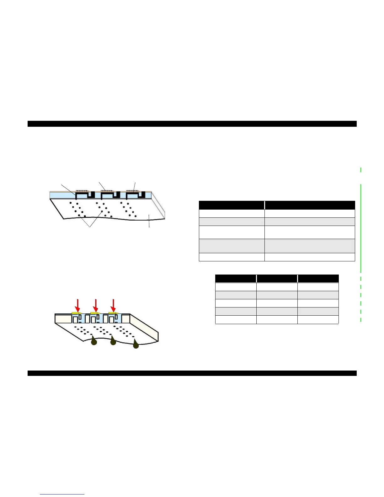
The following figures show sectional drawings of the printhead in the normal and
ejecting states.
1. Normal State:
When no print signal is output, the PZT is in the normal, standby, state.
Figure 2-3. Printhead Normal State
2. Ejecting State:
When a print signal is output from the MAIN board, the IC (IR2C72C: Nozzle
Selector) located on the printhead unit receives the data in 1-byte units. The Nozzle
Selector then sends the voltage signal on to the appropriate PZT. Due to the physical
properties of the PZT, electrical signals cause the PZT to change shape. When the PZT
changes shape, it squeezes the ink cavity, ejecting ink out through the nozzles.
Figure 2-4. Printhead Ejecting State
2.2.3 Carriage Mechanism
The carriage mechanism moves the carriage back and forth according to the drive from
the carriage motor. See Figure 2-6 on the next page.
The carriage motor is a 4-phase, 200-pole, stepping motor and is driven by 2-2 phase,
1-2 phase, Double 1-2 phase, 2-Double 1-2 phase, and 4-Double 1-2 phase drives. This
stepping motor allows the carriage to move freely to fixed positions where necessary
operations such as ink absorption can be performed. The following tables show
carriage the motor specifications and motor controls.
Ink course
Cavity
Nozzles
Nozzle plate
surface
Table 2-2. Carriage Motor Specifications
Items Description
Motor type 4-Phase/200-pole Stepping motor
Drive voltage Range 42VDC ± 5%
Internal coil resistance
7.8 Ohms ± 10%(per phase under 25 °C
environment)
Driving Speed(frequency)
Range[csp(Hz)]
5(60)∼340(4080)
Control method Bi-Polar Drive
Table 2-3. Phase drive
Phase Drive inch/pulse mm/pulse
2-2 1/120 0.212
1-2 1/240 0.106
Double 1-2 1/480 0.053
2-Double 1-2 1/960 0.026
4-Double 1-2 1/1920 0.013
 Loading...