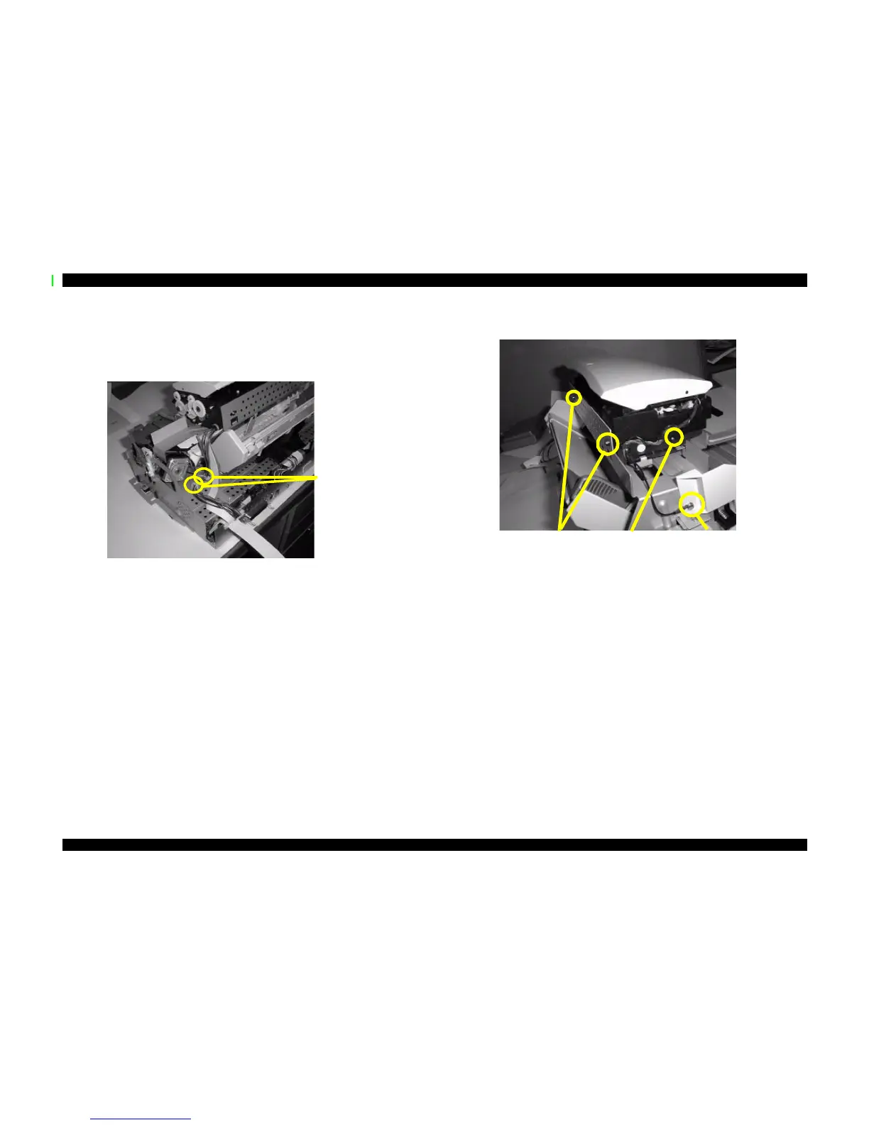
4.2.4 Removing the Scanner Mechanism
1. Remove the housing as described in “Front cover assembly” on page90, “Rear cover”
on page91, and “Upper cover” on page92.
2. Remove the scanner cables from the cable clips as shown below.
3. Slightly pull out the circuit board tray as described in “Removing the Circuit Board
Tray” on page96, and then remove the scanner-related cables from the B101 MAIN
board as described in “Removing the B101 MAIN Board” on page97.
4. Remove one ground screw (CBP 3x6) and three screws (CBP 3x6) securing the
scanner.
5. Slide the scanner slightly toward the CR motor and pull up to remove.
Remove the
cables from
these clips.
Ground connector
and screw
(CBS 3x6)
Remove two screws
(CBP 3x8)
One screw
(CBS 3x6)
 Loading...