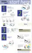
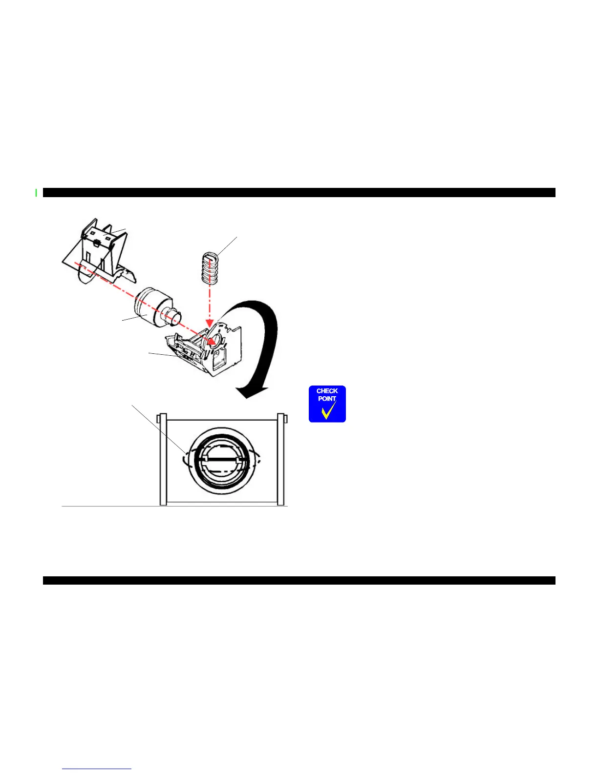
Figure 4-13. Disassembly of Paper Feed Roller Assembly
4.2.5.6 Removing the Carriage Assembly
1. Remove the housing. (Refer to Section 4.2.1)
2. Loosen the timing belt by pushing the driven pulley holder and remove the timing belt
from the pulley of the CR motor side.
3. Take the compression spring 19.6 out of the driven pulley holder.
4. Remove the driven pulley assembly from the driven pulley holder with the timing belt.
Slide the driven pulley holder and remove it from the frame.
5. Remove the torsion spring hanging on the frame and PG lever. Release the fixed hook
of the PG lever and remove the lever.
6. Release the fixed hook of the PG lever support and remove the PG lever support and
washer from the edge of the CR guide shaft. (Refer to the figure next page.)
7. Remove one screw (one CBS Sems R2 3x6) and rotate the right parallelism adjustment
bushing so that it fits in the notch of the frame, and remove it.
8. Remove CR assembly with the CR guide shaft.
Compression Spring 1.66
LD Roller Cover
(Right and Left)
+
Paper Feed Holder
Sheet
LD Roller Assembly
(Right and Left)
Paper Feed Assembly
(Right and Left)
During assembly, set the compression spring
1.66 so that both ends are compressed behind the
hooks as shown here. Then release the hooks
once installed.
n When disassembling the right parallelism adjustment bushing,
mark present location where the bushing is fixed on the frame so
that you can omit gap adjustment after assembly.
n When installing the washer, pay attention to its
direction.(Convex side should face the right parallelism
adjustment bushing side.) Refer to the figure below.
n When installing the PG lever, refer to the figure below.
 Loading...