2.5.1 B101 PSB/PSE Board
The power supply board for the EPSON Stylus Scan 2000 generates +42VDC to drive
the motors, +12VDC to power the lamp, and +5VDC to power the printer logic. The
table below shows application of voltages generated by PSB/PSE board.
1. Even if power is turned off during the middle of a print job, since the driving power is
turned off after the carriage goes back to the carriage lock position, the possibility of
clogged ink nozzle will be decreased.
2. If power is turned off while paper is still being fed in the printer, the same operation
mentioned above is performed and the driving power is turned off after the paper is
completely ejected. The time required is approximately 30 seconds.
Figure 2-23 shows a block diagram of power supply board. The process from the input
of AC voltage to the output of DC voltage is explained in the following pages.
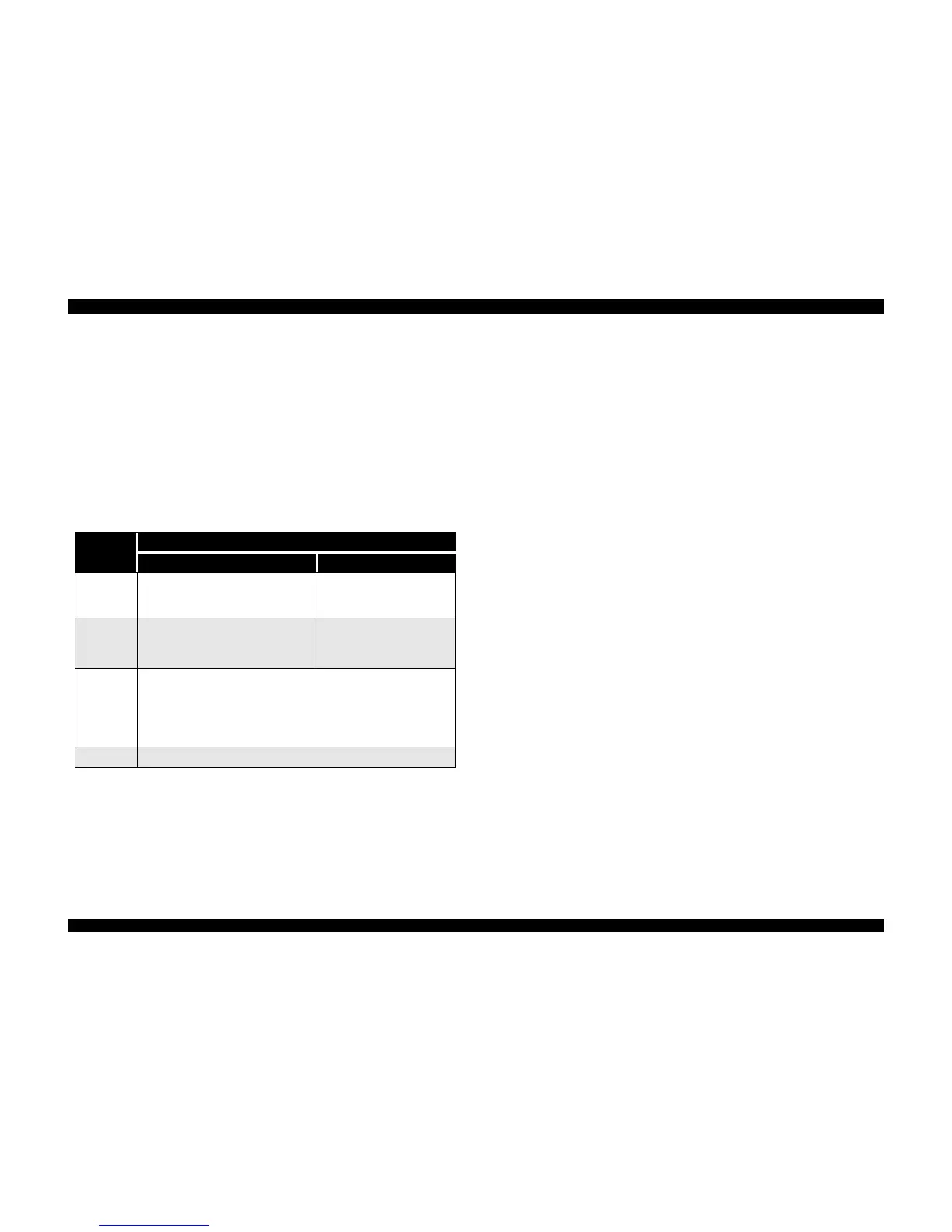
Table 2-12. Application of DC Voltage
Voltage
Application
Printer Scanner
+42VDC
• CR Motor
• PF/Pump Motor
• Printhead drive
+12VDC
ASF motor
Inverter board
CCD sensor board
+5VDC
Common
Control circuit
Sensors (CR HP, PE, ASF)
Control panel
Printhead control
+3.3VDC Control circuit
 Loading...