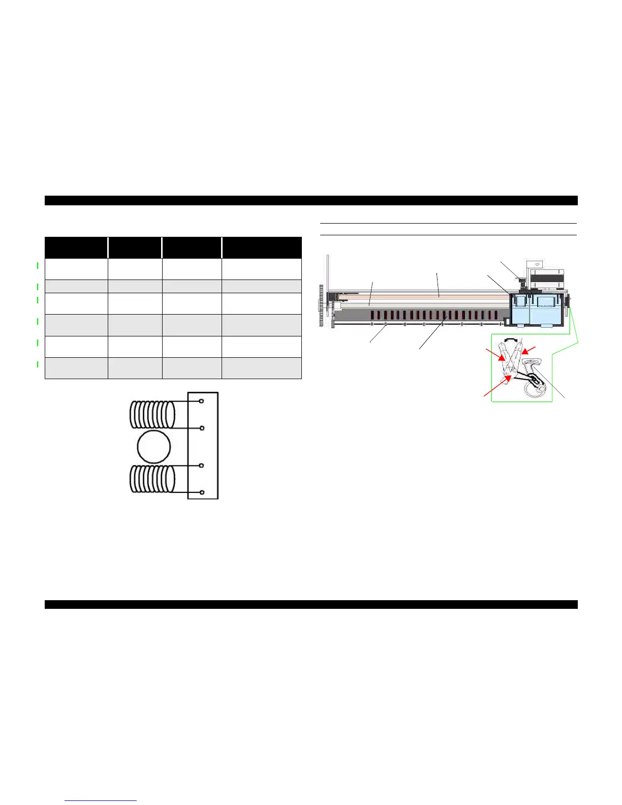
Figure 2-5. CR (PF) Motor Internal Circuit Diagram
PLATEN GAP LEVER
Figure 2-6. Carriage Mechanism with platen gap lever (Top view)
As shown in Figure 2-6, the Platen Gap lever can be moved forward or back to adjust
for the thickness of the paper. The PG lever is connected to the carriage guide shaft,
which raises or lowers the carriage depending on the PG lever position. The nozzle
surface remains parallel to the paper in either position thanks to a tilt adjustment
mechanism. Also, the two parallelism-adjustment levers, one mounted on each side of
the carriage guide shaft, adjust the parallelism between the platen and shaft when the
shaft is installed in the factory. This precise adjustment is necessary to make sure the
gap between the platen surface and the printhead surface is 1.04 mm in the normal
position or 1.74 mm in the thick-paper position.
Table 2-4. Motor Control at Each Mode
Printing mode
Drive Speed
[CPS]
Drive frequency
[PPS]
Drive method
High Speed Skip 340 4080
Double1-2, 2-2,1-2
phase drive*
Normal Printing 200 2400 Double 1-2, 2-2 phase drive
Capping 80 960
2-Double 1-2, 2-2 phase
drive
Wiping 40 480
2-Double 1-2, 2-2 phase
drive
Cap (Valve Release) 20 240
4-Double 1-2, 2-2 phase
drive
Withdrawal of cap 5 60
4-Double 1-2, 2-2 phase
drive
Rotor
1
2
3
4
A
/A
B
/B
Paper eject
rollers
Paper guide
(front)
Forward
(normal)
position
Rear (thick
paper) position
Parallelism
adjust lever
Carriage
motor
Home position
sensor
Carriage
unit
Timing
belt
Paper feed roller
Platen Gap
lever
 Loading...