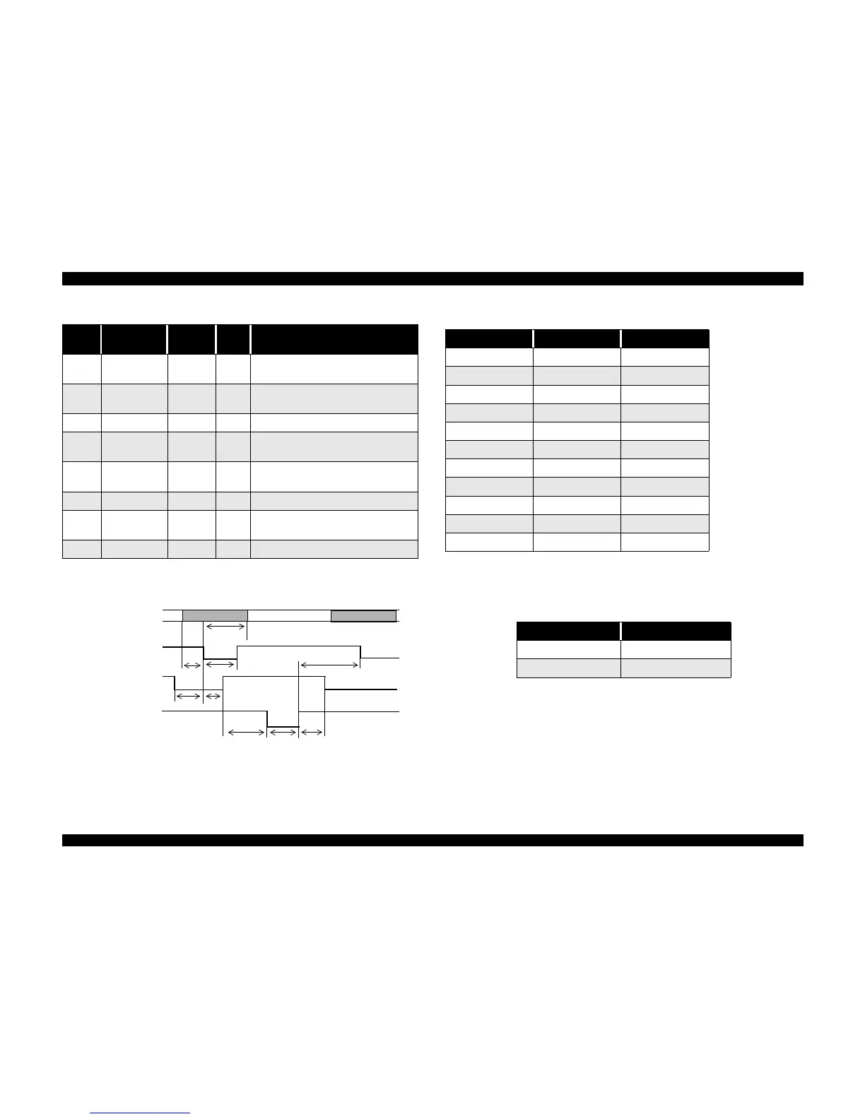
3. Data trans. timing Refer to the IEEE-1284 specification and the following.
* Rise and fall time of every output signal
** Rise and fall time of every input signal
* The Logic H signal goes low, 2.0 V or less, when the printer is turned off and goes high, 3.0
V or more, when the printer is turned on. The receiver shall provide an impedance equivalent
to 7.5 KΩ to ground.
4. Extensibility Request:
The printer responds affirmatively when the extensibility request values are 00H or
04H, which mean
n 00H Request nibble mode reverse channel transfer
31
nReverseReque
st
30 In
This signal goes low to change to the
reverse channel.
32
nPeriphReques
t
29 Out This signal produces a host interrupt.
36 1284-Active 30 In 1284 active signal, High in ECP mode.
18 Periph-Logic H - Out
Always high. Pulled up to +5V via 3.9KΩ
resistor
35 +5V - Out
Always high. Pulled up to +5V via 1.0KΩ
resistor
17 Chassis GND - - Chassis GND
16, 33
19-30
GND - - Signal GND
15,34 NC - - Not connected.
Table 1-4. Reverse channel pin assignments and signals (continued)
Pin # Signal Name
Return
GND pin
In/Out Description
DATA
data byte n
data byte n + 1
-STROBE
BUSY
-ACKNLG
thold
tsetup
tstb
tready
tbusy
treply
tack
tnbusy
tnext
Table 1-5. Data transmission times
Parameter Minimum Maximum
tsetup 500 ns -
thold 500 ns -
tstb 500 ns -
tready 0 -
tbusy - 500 ns
tt-out* - 120 ns
tt-in** - 200 ns
treply 0 -
tack 500 ns 10 us
tnbusy 0 -
tnext 0 -
Table 1-6. Typical tack time
Parallel I/F mode Time required
High speed 1 us
Normal speed 3 us
 Loading...