EasyManuals Logo

Epson VT6-A901S Maintenance Manual

Epson VT6-A901S
196 pages
To Next Page IconTo Next Page
To Previous Page IconTo Previous Page
Page #108 background imageLoading...
Page #108 background image
VT6L Maintenance 12. Joint #4
96 VT series Maintenance Manual Rev.2
(6)
Remove
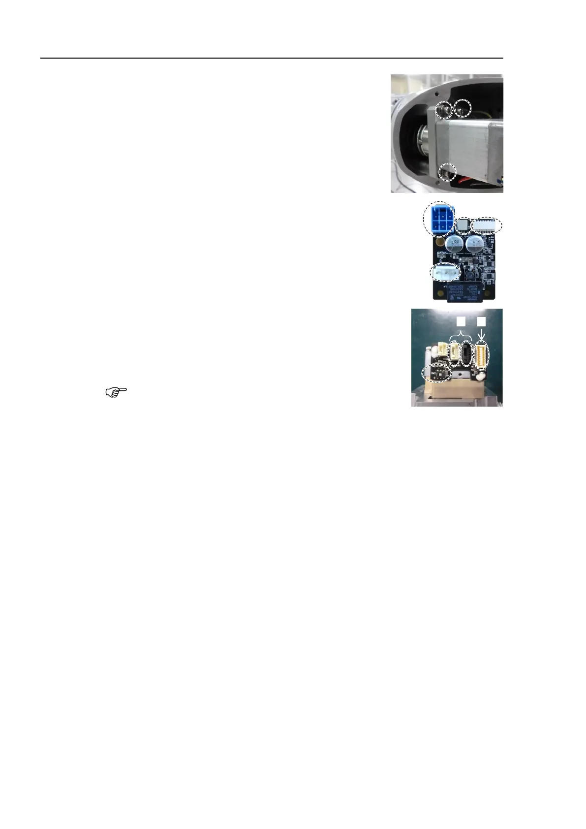
the Joint #4 motor unit.
Hexagon socket head cap bolts: 3-M4×18
(with slotted hole washer)
(7)
Disconnect
the following connectors from the AMP board.
A: Power cable connector
B: Brake connector
C: Signal cable connector (for AMP board)
D: Motor connector
A
B
D
C
(8)
Disconnect
the following connectors of the motor.
A: Signal cable connectors (for motor × 2)
B: Signal cable connector (for AMP board)
The cables will be necessary again.
Be careful not to lose them.
A B
NOTE

Table of Contents

Other manuals for Epson VT6-A901S

Questions and Answers:

Question and Answer IconNeed help?

Do you have a question about the Epson VT6-A901S and is the answer not in the manual?

Epson VT6-A901S Specifications

General IconGeneral
BrandEpson
ModelVT6-A901S
CategoryRobotics
LanguageEnglish

Related product manuals