VT6L Maintenance 2. General Maintenance
VT series Maintenance Manual Rev.2 9
2.3 Tightening Hexagon Socket Head Cap Bolts
Hexagon socket head cap bolts (herein after referred to as bolt) are used in places where
mechanical strength is required. These bolts are fastened with the tightening torques
shown in the following table.
When it is necessary to refasten these bolts in some procedures in this manual (except special
cases as noted), use a torque wrench so that the bolts are fastened with the appropriate
tightening torques as shown below.
Refer below for the set screw.
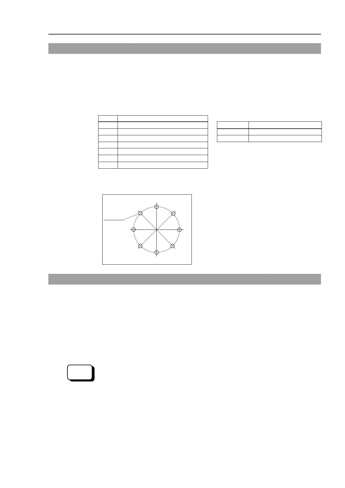
The bolts aligned on a circumference should be fastened in a crisscross pattern as shown in
the figure below.
Do not fasten all bolts securely at one time.
Divide the number of times that the bolts are
fastened into two or three and fasten the bolts
securely with a hex
agonal wrench. Then, use a
torque wrench so that the bolts are fastened with
tightening torques shown in the table above.
2.4 Matching Origins
After parts have been replaced (e.g. motor units, reduction gear units, timing belts), the
Manipulator cannot operate properly because a mismatch exists between the origin stored
in each motor and its corresponding origin stored in the Robot system.
Because of that, it is necessary to perform calibration (encoder rest and calibration) to match
these origins.
For calibration, the pulse values for a specific position must be recorded in advance.
Before replacing parts, select easy point (pose) data from the registered point data to check
the accuracy. Then, follow the steps below to display the pulse values and record them.
Execute the following command from the [Command Window].
>PULSE
PULSE: [Joint #1 Pulse value] pls [Joint #2 Pulse value] pls
pls [Joint #4 Pulse value] pls[Joint #5 Pulse value]pls [Joint #6 Pulse value]pls
 Loading...


