VT6L Maintenance 18. Controller Unit
134 VT series Maintenance Manual Rev.2
18.1 Replacing Controller Unit
WARNING
■
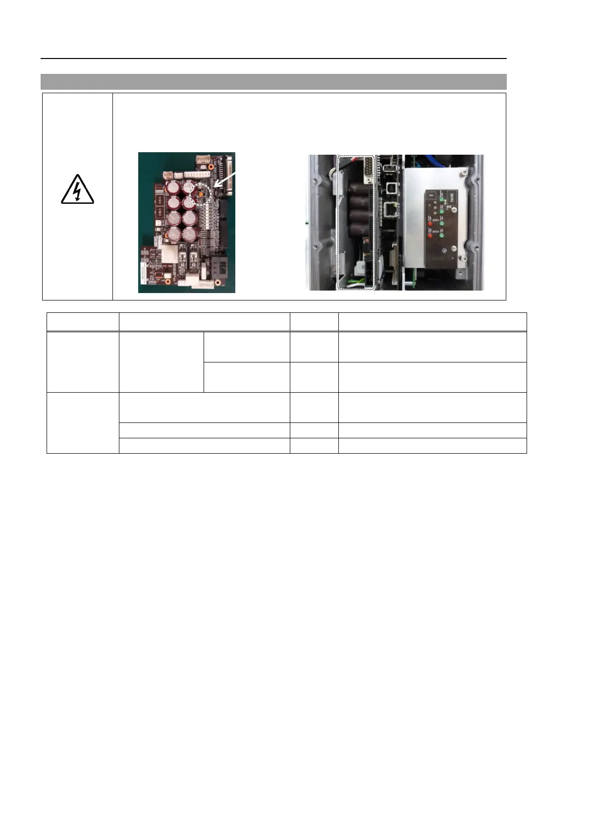
Make sure that orange colored charge confirmation LED on the DPB turns off
ing the Controller Unit. If operating without tuning off the LED, electric
shock or other serious problems for safety may occur.
Maintenance
parts
Controller Unit
AC specification 1
Standard, Cleanroom model: 2194603
Protection model: 2208039
DC specification 1
2207771 (S/N: VT65T02*** only)
2216965 (all DC specification models)
Tools
Hexagonal wrench
(width across flats: 3 mm)
1
For M4 hexagon socket head cap bolts
For tightening torque control
Cross-point screwdriver (No. 2)
The brake is mounted on each joint to prevent the arm from lowering due to its own weight while the Controller
power is OFF or the motor is OFF status. The brake does not work during replacement.
Be careful when performing maintenance work.
 Loading...


