VT6L Maintenance 13. Joint #5
VT series Maintenance Manual Rev.2 109
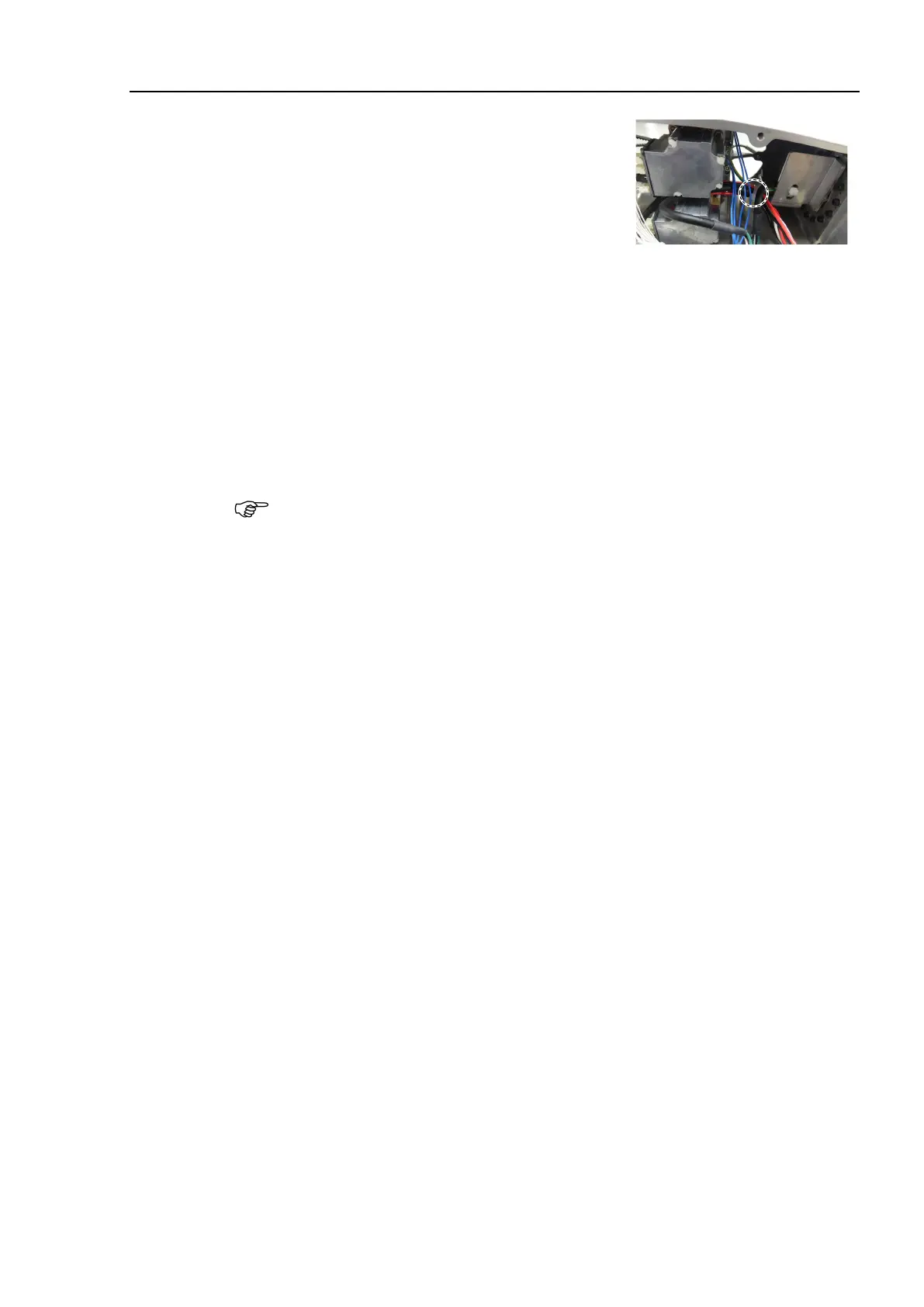
Bind the following cables and the ground wire with
the wire tie.
Wire tie: AB100
Motor cable (Joint #5)
Signal cable (Joint #5)
Motor cable (Joint #6)
Ground wire
Mount the following covers.
Arm #4 Cover 1
Arm #4 Cover 2
Reference: 7. Covers
Reference: VT series Manual VT6L Manipulator 6.5 LED
When starting the Manipulator for the first time after replacing the motor unit, the
motor unit firmware is automatically updated. DO NOT turn OFF the
Manipulator
When you connect a motor unit connected to another axis, an error 5009 or 9709 will
occur. To clear the error, enter the following command in [Command Window] and
execute it.
Joint #1: > MUIDReset 1
Joint #2: > MUIDReset 2
Joint #3: > MUIDReset 3
Joint #4: > MUIDReset 4
Joint #5: > MUIDReset 5
Joint #6: > MUIDReset 6
Reboot the Controller.
Calibrate the Joint #5 and the Joint #6.
Reference: 19. Calibration
 Loading...


