VT6L Maintenance 15. AMP Board
VT series Maintenance Manual Rev.2 123
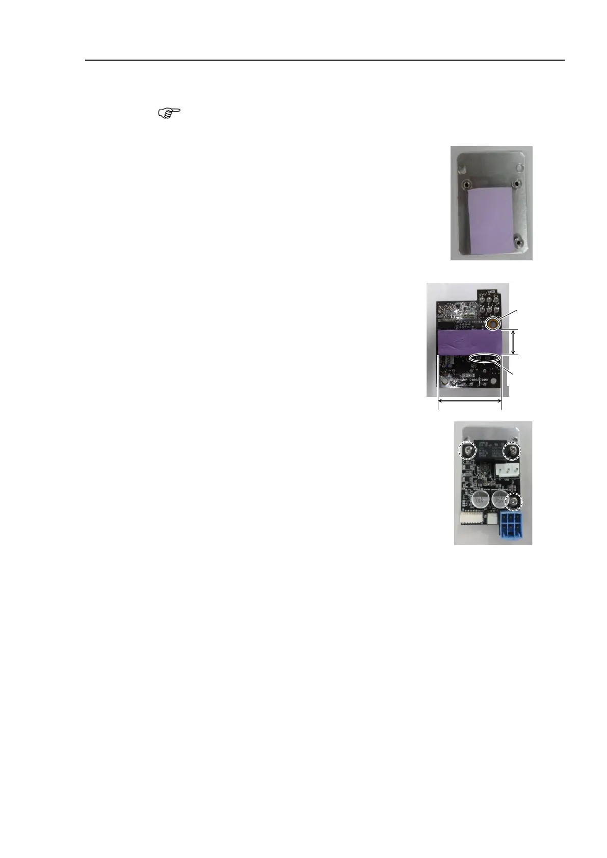
If the thermal conductive sheet is removed in the Removal step (3), attach the sheet.
The size of the thermal conductive sheet varies depending on the shipping time.
the size of the thermal conductive sheet, follow the procedures below
The size of the thermal conductive sheet is
35mm
×24mm:
Attach the thermal conductive sheet on the plate.
Attach the sheet in the direction that the longer
sides of the thermal conductive sheet and the plate
are parallel. As shown in the picture, the attachment
position is inside the range surrounded by three
spacers of the AMP board fixing part.
thermal conductive sheet is
×14mm:
Attach the thermal conductive sheet on the AMP
board.
For the attachment position of the thermal
conductive sheet, refer to the picture on the right.
Be careful not to cover projections and hole.
Mount the AMP board on the plate.
Cross-recessed screws with a washer: 3-M3×6
Tightening torque: 0.45 ± 0.1 N·m
Fix the plate (with AMP board) to the motor unit and mount the motor unit.
Reference: 9.1 Joint #1 Motor Installation
10.1 Joint #2 Motor Installation
11.1 Joint #3 Motor Installation
 Loading...


