VT6L Maintenance 9. Joint #1
VT series Maintenance Manual Rev.2 73
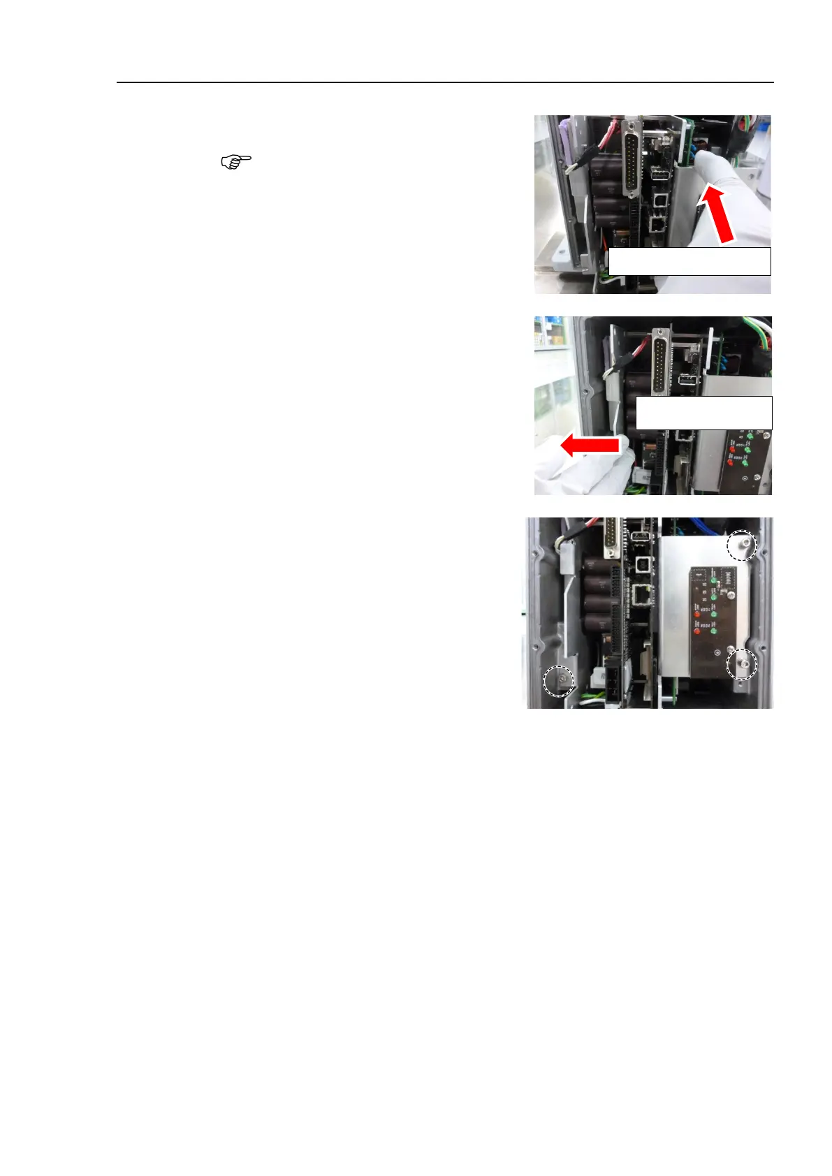
Push the Controller Unit into the
base.
Insert the Controller Unit while moving it
to the right (see the picture).
Then, gently move the plate of the
Controller Unit to the left and let the
thermal conductive sheet contacts with the
wall inside the base.
Move it to the right to insert
Tighten the mounting screws of the
Controller Unit.
Hexagon socket head cap bolts: 3
-M4×10
± 0.2 N·m
Mount the Arm #1 cover and the
connector plate.
Reference: 7. Covers
Reference: VT series Manual VT6L Manipulator 6.5 LED
Reference: 19. Calibration
 Loading...


