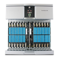
Determining Hardware Status
5-4 SmartEdge 1200 Router Hardware Guide
Table 5-2 lists the LEDs that indicate system-level alarm status.
Determine Card Status with LEDs
Each SmartEdge controller and traffic card has equipment (card) and facility (port) LEDs to indicate
current status of the card and its ports. Additionally, the controller cards have synchronization LEDs to
indicate the status of any externally configured timing sources.
The card LEDs are described in the following sections:
• Controller Cards
•ATM Cards
• Ethernet and Gigabit Ethernet Cards
• SONET/SDH Card
For information about configuring cards and using the SmartEdge OS software to troubleshoot errors, see
the Ports, Circuits, and Tunnels Configuration Guide for the SmartEdge OS.
A2, B2 On Green The zone 2 –48 VDC power source (primary or backup) is present:
• A2—Primary source
• B2—Backup source
Off None The zone 2 (primary or backup) –48 VDC power source is absent.
FAN On Red A failure condition exists in the fan tray.
1
Off None The fan tray is fully functional.
1. The failure can be the result of either a nonfunctional fan or malfunctioning fan controller card; the failure condition can be detected by
the power-on or ODD tests.
Table 5-2 SmartEdge 1200 Alarm LEDs
Label Activity Color Description
ACO
1
2
1. Alarm cutoff (ACO) action can be initiated locally by the ACO button (located directly next to the ACO LED), remotely through an external
ACO contact closure, or through the NetOp™ Element Management System (EMS) software.
2. If more than one source initiates the ACO action, every source that initiated the action must clear the action before the ACO LED is unlit.
On Yellow An audible alarm condition exists but the audible alarm has been silenced.
Off None There is no audible alarm condition or the audible alarm has not been silenced.
CRIT On Red One or more critical alarms exist on the chassis.
Off None No critical alarm exists on the chassis.
MAJ On Red One or more major alarms exist on the chassis.
Off None No major alarm exists on the chassis.
MIN On Yellow One or more minor alarms exist on the chassis.
Off None No minor alarm exists on the chassis.
Table 5-1 SmartEdge 1200 Status LEDs (continued)
Label Activity Color Description

 Loading...