Maintenance
Adjusting the T racking
If y ou push both motion-control lev ers forw ard the
same distance and the mac hine pulls to 1 side , adjust
the trac king as follo ws .
Note: T he messag e displa y sho ws only 2 items at
a time; ho w ev er , the follo wing gures sho w the full
men us for context.
1. P ark the mac hine on a lev el surface , diseng ag e
the PTO , and mo v e the motion-control lev ers
outw ard to the P ark position.
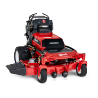
2. In the Main men u, scroll do wn to Ser vice and
press the button .
g376300
Figure 60
3. In the Ser vice men u, scroll do wn to T rac king and
press the button.
g426844
Figure 61
4. Adjust the trac king to the left or right.
Note: Adjusting the trac king to the left causes
the mac hine to steer to w ard the left; adjusting the
trac king to the right causes the mac hine to steer
to w ard the right.
g377650
Figure 62
5. Press the button.
Adjusting the Motion-Control Levers
If the motion-control lev ers do not align horizontally ,
adjust the motion-control lev ers .
1. P ark the mac hine on a lev el surface , diseng ag e
the PTO , and mo v e the motion-control lev ers
outw ard to the P ark position.
2. Shut off the mac hine , remo v e the k ey , and w ait
for all mo ving par ts to stop before lea ving the
operating position.
3. T ur n the batter y-disconnect switc h to the Off
position.
4. Push the motion-control lev ers do wn out of the
P ark position.
g376309
Figure 63
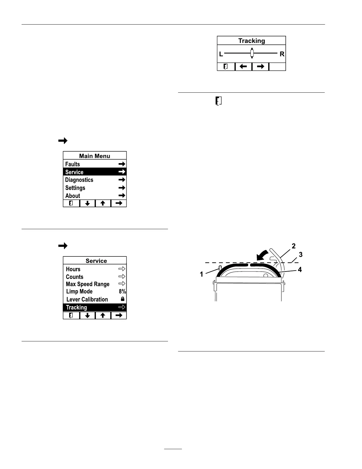
1. Left motion-control lever 3. Check the horizontal
alignment here
2. Right motion-control
lever in the Park position
4. Right motion-control
lever
5. Chec k the horizontal alignment of both lev ers b y
using the front or rear reference bar as a guide .
Note: If a lev er is not aligned, proceed to ste p 6
to adjust the cam for that lev er .
6. R elease the cushion from the rear of the mac hine
and remo v e the rear access co v er .
7. Loosen the bolt holding the cam.
44
 Loading...