Maintenance
Matching the Height-of-Cut
1. Chec k the rear tire pressure .
2. Set the height-of-cut to the 76 cm (3 inc h)
position.
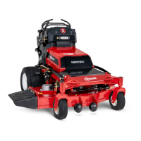
3. With the mac hine on lev el surface , position 1
blade front-to-rear .
4. Measure at A , and from a lev el surface to the
cutting edg e of the blade tips .
Note: T he measurement should be 76 cm (3
inc hes).
g000975
Figure 75
1. Measure from a level
surface
2. Measure the blade at
point A
5. If the measurement is not cor rect, locate the front
2 y ok es on the mac hine .
6. Loosen the side bolt and jam n ut of the y ok es .
7. Adjust the top bolt of the y ok es until the blade
tips matc h 76 cm (3 inc hes).
8. Tighten the jam n uts and side bolts .
Adjusting the Deck-Lift Spring
Note: Adjusting the compression spring alters ho w
m uc h the dec k oats and the amount of effor t needed
to lift the dec k when using the height-of-cut lev er .
• More spring extension reduces the lev er lift force
required and causes the dec k to oat more .
• Less spring extension increases the lev er lift force
required and causes the dec k to oat less .
1. Raise the height-of-cut lev er and loc k it into the
transpor t position.
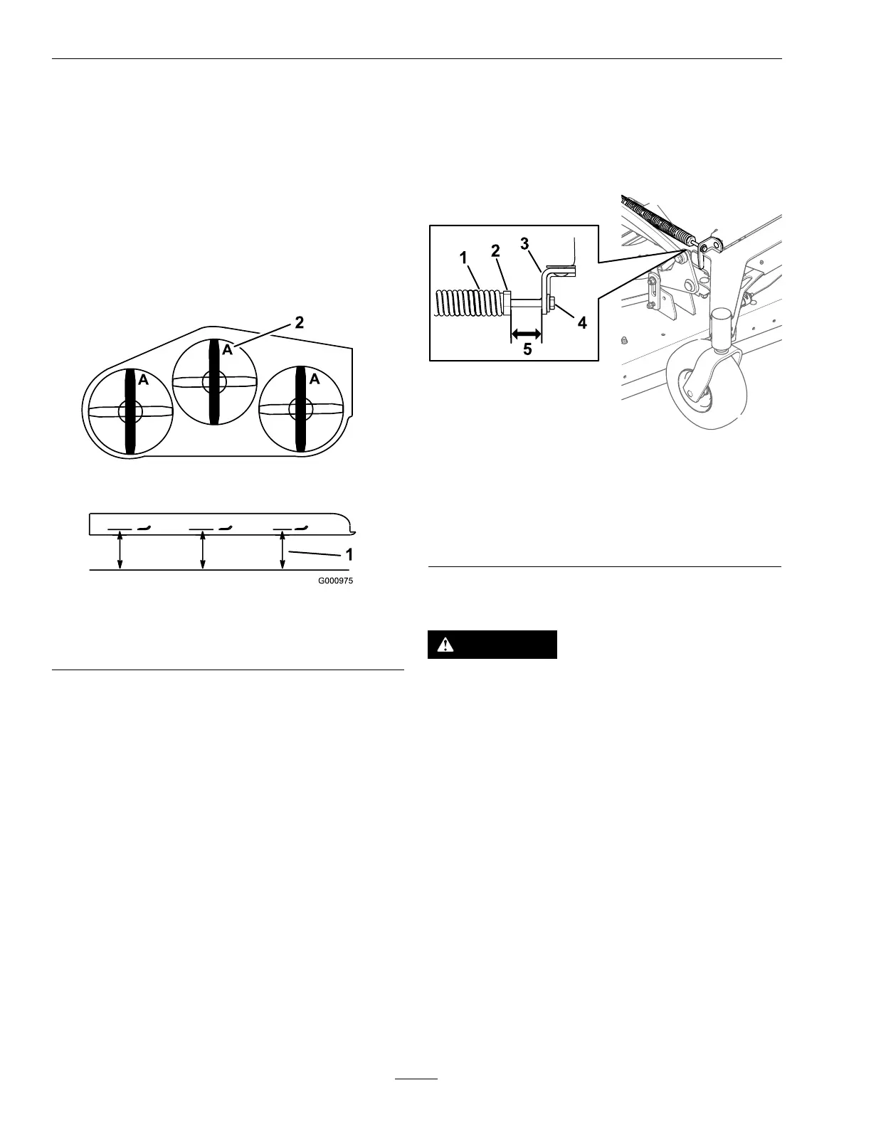
2. V erify that the distance betw een the spring n ut
and the rear side of the w elded mount brac k et is
41 mm (1-5/8 inc h).
3. If needed, adjust the distance b y adjusting the bolt
on the front of the mount brac k et.
g377366
Figure 76
1. Deck-lift spring
4. Adjustment bolt
2. Spring nut 5. Length is 41 mm (1-5/8
inch).
3. Rear side of the mount
bracket
Replacing the Grass Deector
DANGER
An unco v er ed discharge opening allo ws objects
to be thr o wn to w ard y ou or bystander s. Also,
contact with the blade could occur . T hr o wn
objects or blade contact will cause serious injur y
or death.
Do not operate the mo w er with the discharge
deector raised, r emo v ed, or alter ed unless a
g rass collection system or mulch kit is in place
and w or king pr oper l y .
1. R emo v e and retain the loc kn ut, bolt, spring, and
spacer holding the deector to the dec k brac k ets .
2. R emo v e the damag ed or w or n g rass deector .
Inspect the mounting hardw are and re place if
necessar y .
3. Inser t the bolt through the dec k tab and new
g rass deector tab . Install the spacer and spring
onto the bolt.
50
 Loading...