6 If you are mounting the switch in a four-post rack or a cabinet, secure the rear mounting brackets
(rails).
Otherwise, skip to step 7 on page 184.
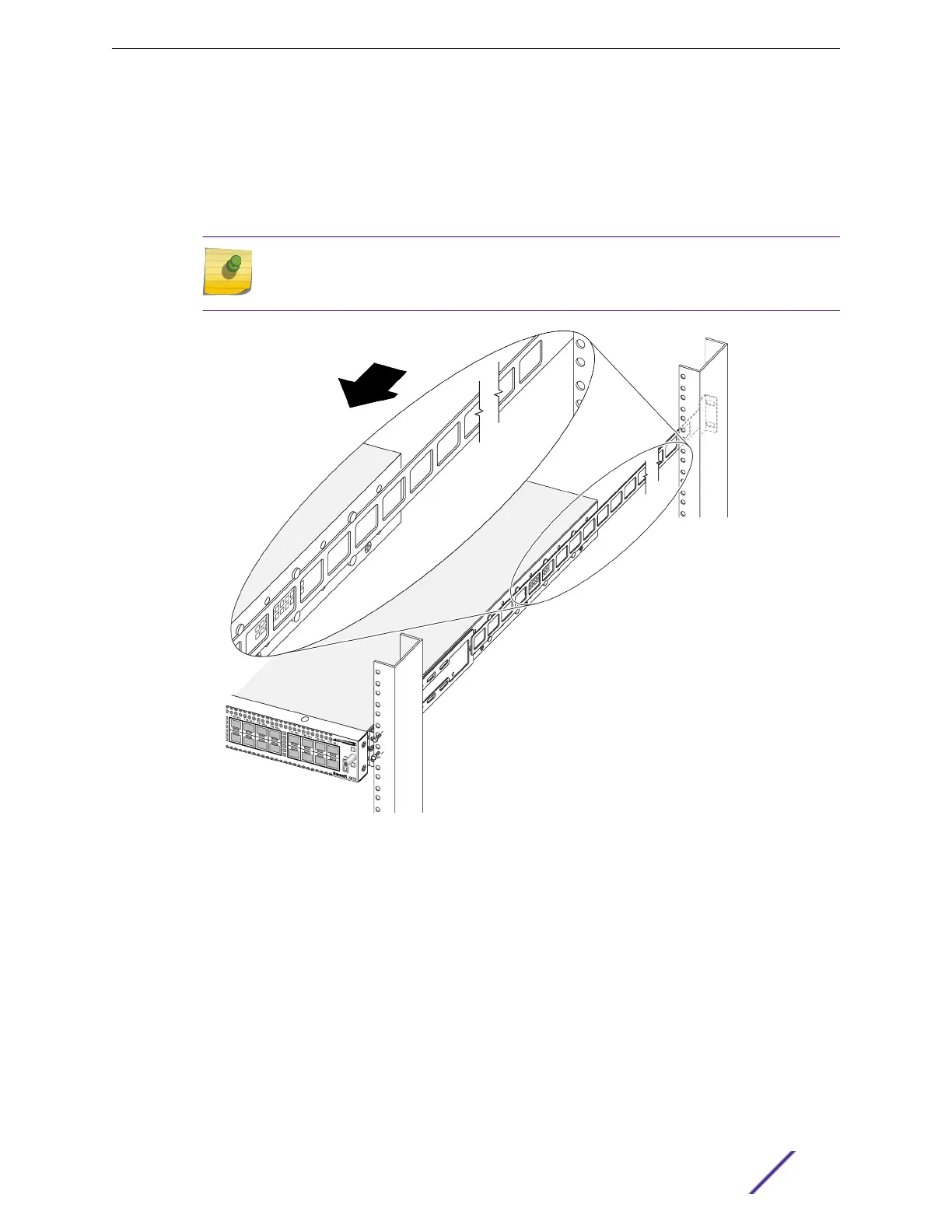
a At the rear of the rack or cabinet, for each side, slide the rails between the two rows of pegs on
either side of the switch.
Note
It is best practice to extend the rear rails no more than 33 inches (83cm) from the front
of the chassis.
Figure 137: Inserting the Rear Mounting Brackets Between the Pegs on the Side
of the Switch
b Secure the rear mounting brackets to the rack posts using suitable screws.
Be sure the switch is level.
7 If a grounding lug is present, ground the switch.
For X450-G2 series switches, ground the switch as follows:
a At one end of the wire, strip the insulation to expose 1/2 inch (12 mm) of bare wire.
b Identify the grounding lug on the back of the switch.
c Insert the stripped wire into the grounding lug.
d Using a straight-tip torque screwdriver, tighten the retaining screw to 20 in‑lb (2.25 N m).
e Connect the other end of the wire to a known reliable earth ground point at your site.
Installing Your Extreme Networks Switch
ExtremeSwitching and Summit Switches: Hardware Installation Guide 184
 Loading...


