5 Insert the DC power cables into the connector.
a Slide the end of the positive wire (–48 V RTN) into the positive terminal (labeled +, on the left
side of the connector).
b Tighten the screw on the top of the positive terminal connector to between 4.4 in‑lb (0.50 N m)
and 7.1 in‑lb (0.8 N m).
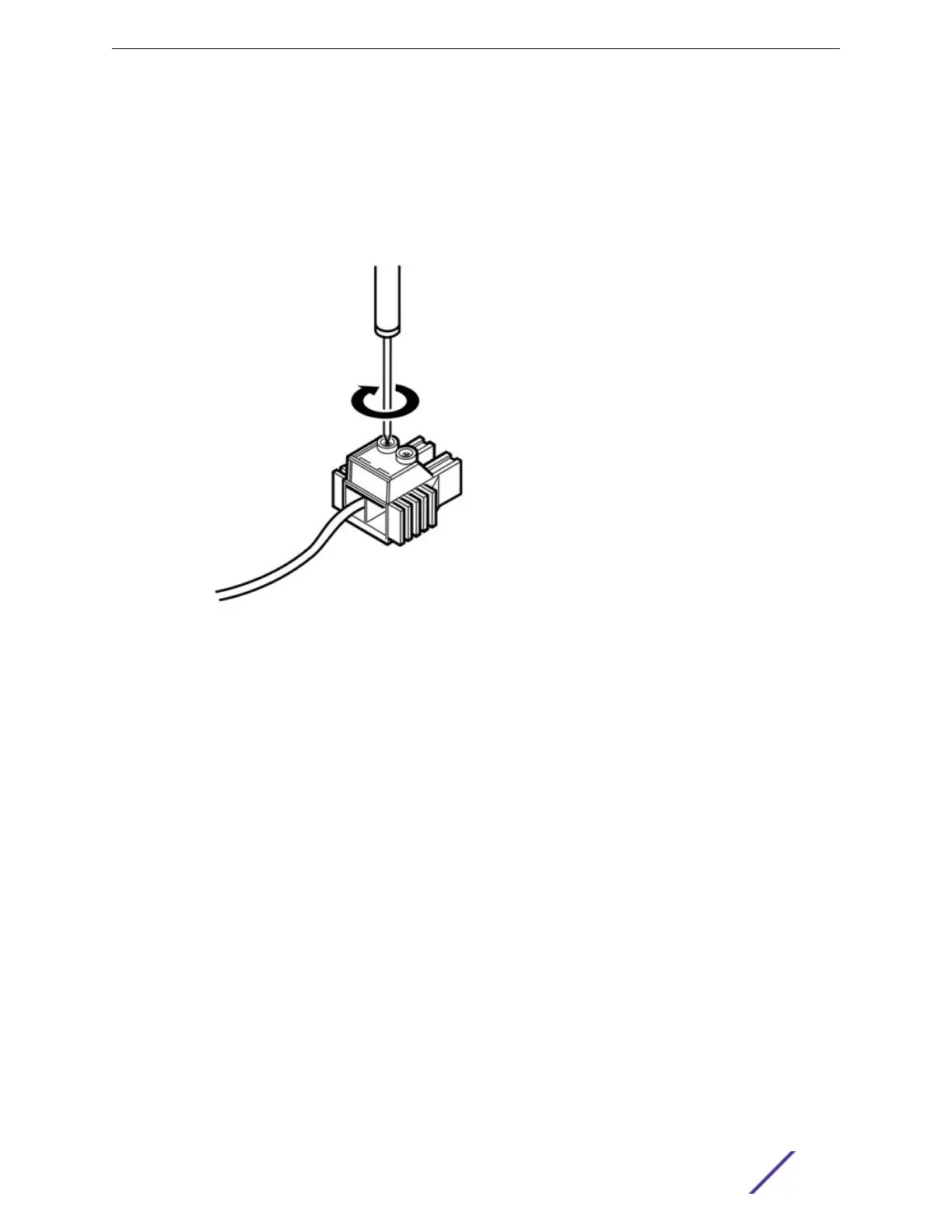
See Figure 242.
Figure 242: Inserting the DC Power Cables into the Connector
c Slide the end of the negative wire (–48 V) into the negative terminal (labeled –, on the right side
of the connector).
d Tighten the screw on the top of the negative terminal connector to between 4.4 in‑lb (0.50 N m)
and 7.1 in‑lb (0.8 N m).
Replacing DC Power Supplies
ExtremeSwitching and Summit Switches: Hardware Installation Guide 304
 Loading...


