QS-1VTG 400/400D • Quick Start
Quick Start — VTG 400/400D
Installation
CAUTION
Operation and service must be
performed by authorized personnel
only. These units must be operated
in accordance with national and local
electrical codes.
Step 1
Turn off power to the video test generator and any
output devices, and remove power cords from
them.
Step 2
If desired, install the four rubber feet on the bottom
of the VTG.
Step 3
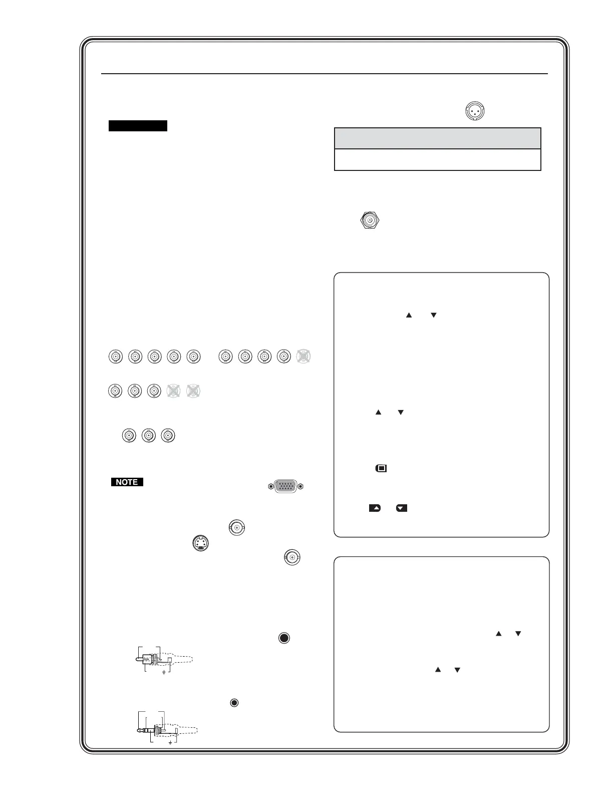
Rear panel video outputs
Attach output devices to the VTG.
For RGBHV, RGBS, RGsB, or RsGsBs output:
For R-Y, Y, B-Y component output:
The 15-pin HD RGB output
connector will output
RGBHV, RGBS, RGsB, and
RsGsBs.
For composite video output:
For S-video output:
For SDI/HDSDI output (VTG 400D only):
Step 4
Rear panel audio outputs
Attach audio output devices to the VTG. Wire the
connectors as shown below.
RCA (unbalanced mono audio) output 1:
3.5 mm mini phone jack (unbalanced mono left
and right channels) output 2:
RGBHV output
RGBS output
R
G
B
V
H
/HV
R
G
B
V
H
/HV
R
G
B
V
H
/HV
RGsB, RsGsBs output
Component video output
(R-Y, Y, B-Y)
R-Y
Y
B-Y
COMPOSITE
S-VIDEO
RGB
SDI/HDSDI
1
2
3
Tip (+)
Sleeve ( )
RCA Connector
XLR (balanced mono) output 3:
Scope Trigger
When using an oscilloscope, connect the scope’s
external trigger to the trigger connector of the
VTG.
Sleeve ( )
Ring (R)
Tip (L)
Application Pin 1 Pin 2 Pin 3
Balanced audio (std.)
gnd (shield) positive (+) negative (-)
(on sending/female connector) (hot/live) (cold/return)
3-pin XLR Pin Configuration
Operation
TRIGGER
Video Adjustments
Test pattern selection buttons
Depending on the currently selected video rate, press the
Video Test Pattern and selection buttons to select from
up to 28 different video test patterns. The newly selected
test pattern will display on the LCD for 3 seconds before
returning to the previous menu. Refer to the Test Pattern
Chart in Appendix A of the user’s manual for the table of
available test patterns and their features.
Video output range button
Press the Video Range button to select from among eight
output range categories.
Video output rate buttons
Press the and Video Rate buttons to select an output
rate for the chosen output range. The output rates are
displayed two-at-a-time on the LCD. After choosing the
desired rate, press the Select button to activate the
highlighted rate.
Test pattern invert
/
special function button
Press the button to toggle the selected test pattern
between normal and inverted (special) state (when
available).
Video level adjustment buttons
Use the and buttons (next to pattern name) to adjust
the test pattern’s video level between 0% (0 IRE) and 100%
(100 IRE), when available.
Audio Adjustments
Signal type selection button
The VTG 400/400D can selectively output seven different
audio signal formats: pink noise, white noise, sine wave,
square wave, frequency sweep, polarity test, and sine burst.
Audio level selection buttons
The RMS audio output level for each audio signal type is
adjusted between a range of values using the or Level
buttons.
Audio frequency selection buttons
The frequency for each audio signal type is adjusted between
a range of values using the or Audio Frequency
buttons. The following frequencies are available for the signal
types below:
• Sine wave and sine burst: 20 Hz - 20 kHz in 1/12 octave
steps
• Square wave: 20 Hz - 5 kHz in 1/12 octave steps
• Frequency sweep speed: 1 - 120 seconds
Tel. 07131 911201
Fax 07131 911203