Installation and Operation, cont’d
VTG 400/400D • Installation and Operation2-24
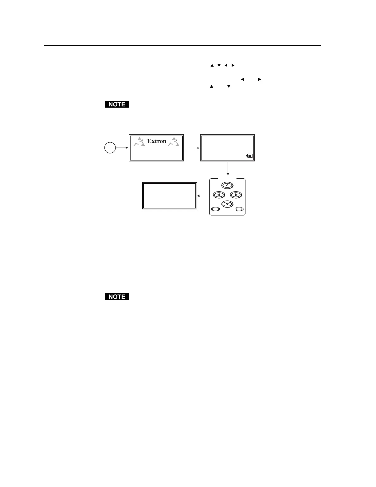
Press the Scope Trigger Cursor buttons ( , , , ) to position the oscilloscope’s
cursor on a line (y-axis) of video and on a specific pixel (x-axis) of that line. This
x-y coodinate location is the trigger point. Use the
and buttons to position
the cursor along the x-axis, and use the
and buttons to position the cursor
along the y-axis.
Positioning the cursor outside of the scan rate limits for the active area
results in an “N/A” display for the coordinate value and the cursor is no
longer visible in the display, but the scope trigger is still active.
SCOPE — TRIGGER
Position: Active (0004,0004)
Total (0300,0039)
Cursor: Invisible On Screen
Shape = Single Pixel
Press any Scope
Trigger button.
Power
on
RES: VGA 640x480
FRQ: 31.50kHz 60.00Hz
PAT: Fine Crosshatch
SIG: Pink noise FRQ: N/A
LEV: -10 dBu 245mV
VTG 400
VIDEO TEST GENERATOR
60-564-01 Ver. 0.00
3 sec.
SCOPE-TRIGGER
CURSOR
SHAPE HIDE??
Scope trigger menu
Press the Scope Trigger Shape button to toggle the on-screen cursor between a
crosshair (useful for locating the cursor on the display screen) and single pixel
(useful for locating the cursor on the oscilloscope screen).
Press the Scope Trigger Hide button to turn the cursor on or off.
An example of a crosshair trigger point on a flat field test pattern is shown in the
following figure.
When doing a screen capture, hiding the cursor is recommended. A hidden
cursor can still be used to change the position of the trigger point.
Tel. 07131 911201
Fax 07131 911203