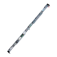
A1400 AIR 5 532129 04 - Rev.B
Translation of the original instructions
ENGLISH
CONTENTS
EC Declaration of conformity of a machine ................... 3
EC Declaration of conformity ................................... 3
Declaration of incorporation of partly completed machinery 4
Declaration of incorporation for partly completed machinery
4
1. INTRODUCTION TO THE MANUAL .............................. 7
1.1 Safety recommendations ........................................ 7
Safety of the installer/maintenance technician .............. 7
Workplace safety ................................................ 7
User safety ........................................................ 7
1.2 Meaning of the symbols used ................................... 8
2. AUTOMATION A1400 AIR H100H140 ...................... 10
2.1 Intended use .....................................................10
Limitations for use ..............................................10
2.2 Unauthorised use ................................................10
2.3 Identification plate ..............................................11
2.4 A1400 AIR KIT DM identification plate ........................11
2.5 Technical specifications A1400 AIR ............................ 12
2.6 Technical specifications A1400 AIR DM .......................13
2.7 Types of system supplied .......................................14
Installation according to the type of system supplied ......14
Automation components A1400 AIR ......................... 15
A1400 AIR DM KIT components ...............................16
ACCESSORIES ................................................... 17
3. INSPECTION AND PREPARATION ............................ 18
3.1 Preliminary inspection ..........................................18
3.2 Arrangement of electrical cables ..............................18
4. TRANSPORT AND RECEIPT OF THE GOODS ................ 19
Handle packages................................................19
Unpack and Handle.............................................19
5. CUTTING THE PROFILES ........................................ 20
6. ASSEMBLING THE HEAD SECTION ........................... 21
6.1 Preparing the self-supporting head section (if used) ........21
6.2 Assembling the components ...................................22
Mechanical stops
...............................................22
Electronics module .............................................23
Safety cables and spacers ...................................... 24
Motor.............................................................24
Return PULLEY ..................................................24
Motor release monitor .........................................26
Internal release ..................................................26
Motor block operation test XB LOCK .........................26
Cover drilling ....................................................27
Closed door monitor sensor ...................................27
Emergency battery kit .........................................27
7. ASSEMBLING THE A1400 AIR CS FRAME.................... 28
7.1 Entry with TK50 profiles .........................................28
Preliminary operations .........................................28
Assembling the frame ..........................................28
Fastening the fixed leaves .....................................29
Mounting mobile leaves .......................................29
Glazing installation .............................................29
Assembly of the head section to the upper profile .........29
7.2 Entry door with TK20 profiles ..................................29
Preliminary operations .........................................29
Assembling the frame ..........................................30
Mounting MOBILE LEAVES ....................................30
Assembly of the head section to the upper profile .........30
8. INSTALLING THE HEAD SECTION ............................. 31
8.1 Preliminary operations ..........................................31
8.2 Wall fastening ....................................................31
8.3 Mounting the self-supporting automation ...................32
8.4 Mount the transom ..............................................33
9. INSTALLING THE LEAVES ....................................... 34
9.1 Mounting the lower shoes ......................................34
SHOE WITH TK50 BRACKET .................................... 34
TK50 SWIVEL SHOE .............................................34
SHOE WITH TK20 BRACKET ....................................
34
9.2 Mount profiles on the leaves ...................................35
9.3 Mount the lower sweeper ......................................35
Glass leaves ......................................................35
9.4 Installing the leaves .............................................35
9.5 Adjusting the leaves and carriages ............................37
Height of the leaves ............................................37
Depth of the leaves .............................................37
Counter wheel ..................................................37
10. INSTALLING THE GLASS LEAVES ............................ 38
10.1 Installing wheels on the A1400 AIR DM .....................40
10.2 Mounting the brushes .........................................41
11. ASSEMBLE THE BELT, CASING AND ACCESSORIES ...... 42
11.1 Mounting the belt ..............................................42
Adjusting the belt ..............................................44
11.2 Belt tensioning .................................................45
11.3 Belt tensioning with the A1400 AIR KIT DM ..............46
11.4 Adjusting the mechanical stops ..............................47
Stops on opening ...............................................47
Double leaf closing stops ......................................47
Single leaf closing stops........................................47
11.5 Mounting the side profiles ....................................48
11.6 Installing the casing brackets .................................48
11.7 Fitting the cover ................................................49
11.8 Installing the Motor block XB LOCK ..........................50
11.9 Adjusting the XB LOCK motor block..........................50
11.10 Aligning the XB LOCK motor block .........................51
11.12 Mounting the cable gland guides ..........................51
12. ELECTRONICS INSTALLATION E1SL ........................ 52
12.1 Electronic module E1SL .......................................52
Electronic board E1SL ..........................................52
12.2 Terminal boards and connectors .............................54
J1 J4 - INPUTS S1-S2 ............................................54
J7 - INPUTS E1 -E2
...............................................54
J8 - SDLKKS EVOEVO EVO-54-KS EVO ........................54
J9 - XFA button photocells .....................................54
J10 - Main power supply 36V - 4A .............................54
J11 - Motor .......................................................55
J12 - Motor Encoder ............................................55
J13 - XB XM LOCKOCK/ 55 motor block and monitoring
(OPTIONAL) ...................................................... 55
J14 - Emergency battery .......................................55
J17 - USB Port .................................................... 55
J18 - INTERCOM .................................................55
J21 - Inputs i1-i2-i3-i4 .........................................55
J22 - Configurable outputs .................................... 55
J23 J24 J25 - Optional modules ...............................55
12.3 Motor and encoder ............................................56
12.4 XB LOCK motor block and monitoring (OPTIONAL) ........56
12.6 Installing the A1400 AIR DM electronic board ..............58
12.7 Connecting the 2
nd
motor ...................................59
12.8 XV1-XDT1 EXIT and entry detectors .........................60
12.9 2 XDT1 Exit detectors and 2 XDT1 ENTRY detectors ........61
12.10 XBFA Detectors for safety in OPENING .....................62

 Loading...