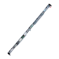
A1400 AIR 116 532129 04 - Rev.B
C
I
Lt
B
Vp
130
Vp Lt B I C D
700 1500 515 1150 150 2470
800 1700 615 1200 150 2570
900 1900 715 1250 150 2670
1000 2100 815 1300 150 2770
1100 2300 915 1350 150 2870
1200 2500 1015 1400 150 2970
1300 2700 1115 1450 150 3070
1400 2900 1215 1500 150 3170
1500 3100 1315 1550 150 3270
1600 3300 1415 1600 150 3370
1700 3500 1515 1650 150 3470
1800 3700 1615 1700 150 3570
Vp Lt B I C D
1900 3900 1715 1750 150 3670
2000 4100 1815 1800 150 3770
2100 4300 1915 1850 150 3870
2200 4500 2015 1900 150 3970
2300 4700 2115 1950 150 4070
2400 4900 2215 2000 150 4170
2500 5100 2315 2050 150 4270
2600 5300 2415 2100 150 4370
2700 5500 2515 2150 150 4470
2800 5700 2615 2200 150 4570
2900 5900 2715 2250 150 4670
3000 6100 2815 2300 150 4770
118
Lt = Vp X 2 + 100
Translation of the original instructions
ENGLISH
Return pulley
Motor 1
Control
board
Power supply
Emergency
batteries
24.2 POSITION OF COMPONENTS ON A1400 AIR SUPPORT PROFILE
A1400 AIR RIGHT OPENING SINGLE LEAF
B = Carriage fixing distance on the sliding leaf
C = Motor position
D = Transmission belt length
I = Motor / transmission unit centre distance
Lt = Head section length
Vp = Free passage opening
100 = leaf overlap (mm)

 Loading...