A1400 AIR 52 532129 04 - Rev.B
0.0
RESET/SETUP
DL2
DL11
MAIN
F1
USB
+
-
F
ERR
BAT1
OPEN
EMERG
BAT2
SIC
_
OP
SIC
_
CL
J10
J14
J11
J12
J13
V G
S1
G
T
J
J17
V RX TX G
J8
E1 G E2
J7
T1 G
T2
R1
G R2
J9
V G 01 02 02
J22
J21
V
G
I1
I2
G
I3
I4
V
J18
G CH CL G
J23J24
J25
V G
S2
G
T
J4
0.0
RESET/SETUP
DL2
DL11
MAIN
F1
USB
+
-
F
ERR
BAT1
OPEN
EMERG
BAT2
SIC
_
OP
SIC
_
CL
J10
J14
J11
J12
J13
V G
S1
G
T
J
J17
V RX TX G
J8
E1 G E2
J7
T1 G
T2
R1
G R2
J9
V G 01 02 02
J22
J21
V
G
I1
I2
G
I3
I4
V
J18
G CH CL G
J23J24
J25
V G
S2
G
T
J4
SW1
SETUP RESET
SW3
+
SW4
F
SW2
-
73
74
Translation of the original instructions
ENGLISH
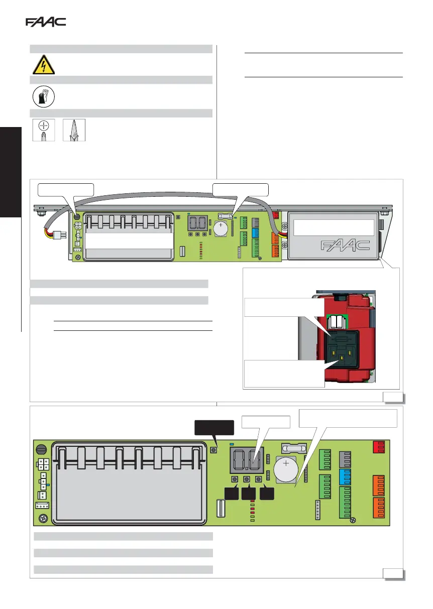
12. ELECTRONICS INSTALLATION E1SL
POWER SUPPLY UNIT
E1SL ELECTRONIC BOARD
Fuse F1 Fuse F2
Buttons
SW1 SETUP / RESET
SW2
-
” (scrolls programming values)
SW3 “+” (scrolls programming values)
SW4 “F” (programming: scrolls functions/confirms values)
Display
Clock battery: lithium 3V CR2032
(NOT SUPPLIED)
ELECTRONIC BOARD E1SL
RISKS
PERSONAL PROTECTIVE EQUIPMENT
REQUIRED TOOLS
2.5
F
ALWAYS DISCONNECT THE POWER SUPPLY before working on the board.
Turn the power on only after having completed all the connections and
preliminary start-up checks (64).
12.1 ELECTRONIC MODULE E1SL
Switching power supply unit 230 V~ +6% -10%
self-protected from overloads
Mains power supply input
(230V~ +6% -10%)
Fuse F3 (extractable support)
Fuses
F1 battery protection 8 A T (delayed)
F2 accessory protection 2 A F (quick)
F3 power supply unit primary protection 2.5 A T (delayed)
A spare fuse is provided (in the extractable support)