A1400 AIR 32 532129 04 - Rev.B
30
31
29
1
1
1
1
Translation of the original instructions
ENGLISH
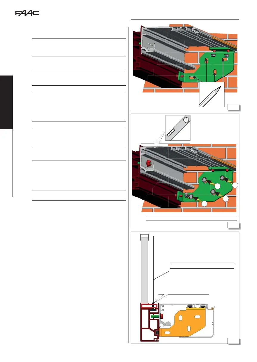
8.3 MOUNTING THE SELFSUPPORTING
AUTOMATION
IF PROVIDED)
!
The side supporting walls must be adequate for the weight of the entry
door (automation with leaves). It is recommended to use dowels with
adequate screws and tightening torque.
In the self-supporting version of the automation system (if supplied),
the support profile is mounted on the self-supporting profile and the
side brackets 21.
1. Lift the automation to the established fastening height and mark
on the wall the drilling points at the 4 slots of each side bracket.
!
Check the horizontal with a spirit level.
2. Drill the holes on the side walls.
- Use drill bits that are suitable for the material 29.
3. Lift the automation and fasten it to the side walls:
- Use 4 suitable wall plugs in correspondence with the 4 slots on
each of the two side brackets 30.
!
Check the horizontal with a spirit level.
4. If the length of the profile exceeds 3000 mm, tie rods must be fitted
to the wall or ceiling, depending on the situation, in intermediate
position to prevent bending of the head section’s middle.
!
Use steel tie rods suitable for supporting a 600 kg load (the contact
surface of the cable with the self-supporting profile must be at least 70
mm
2
)* 31.
5. The number of tie rods required depends on the length of the
profile:
- from 3000 to 4000 mm, a central fastening is required.
- from 4000 to 6100 mm, two intermediate fastening points are
required.
It is nevertheless recommended to fit a tie rod in a central position also
for lengths less than 3000 mm.
Screws and dowels not supplied.
* minimum 70 mm
2
Tie rod not supplied.