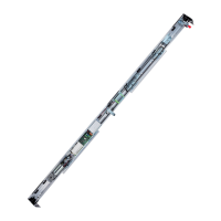
A1400 AIR 113 532129 04 - Rev.B
115
Translation of the original instructions
ENGLISH
24.1 INSTALLATION DIAGRAMS
A1400 AIR H100 - H140
INTERNAL
VP Free passage opening width
LF distance between fixed sides
LA mobile leaf width
X distance to prevent finger trapping (only if G>8mm) / min.
25 mm
LC = LT casing and head section width
HVP passage opening height
HA mobile leaf height
GP floor guide
INTERNAL
Leaves closed
Leaves open
Casing H100
Casing H140

 Loading...