A1400 AIR 56 532129 04 - Rev.B
J12
J11
T1 G
T2
R1
G R2
J9
V G 01 02 02
J22
V
G
I1
I2
G
I3
I4
V
J18
G CH CL G
V G
S2
G
T
J4
J13
77
78
1
2
B
C
1
2
2
3
1
A
B
C
J13
2
1
2
3
4
5
Translation of the original instructions
ENGLISH
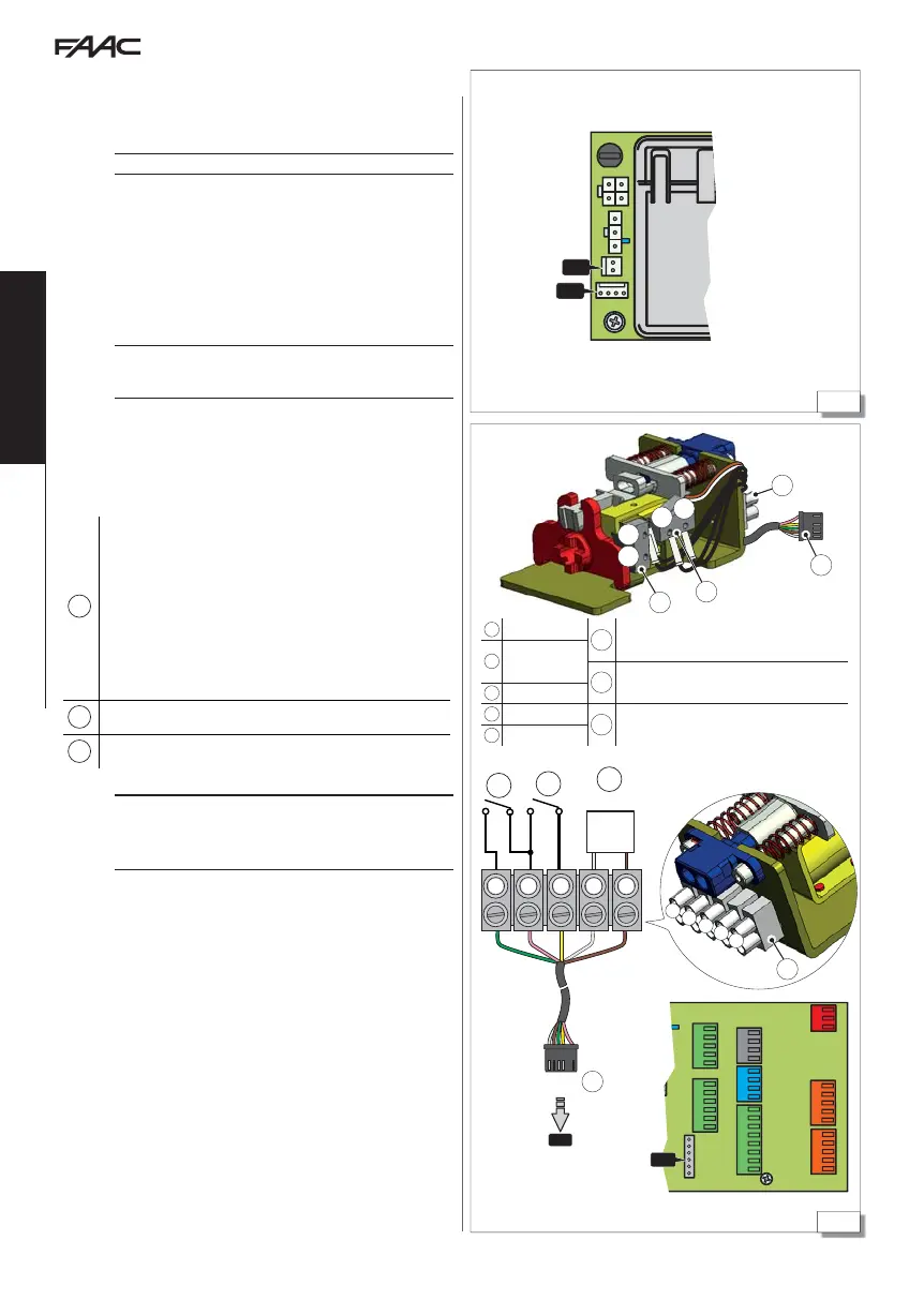
12.3 MOTOR AND ENCODER
1. Connect motor M1 to connector J11.
2. Connect the encoder cable of motor M1 to connector J12. 77
!
WARNING: TEST THE ENCODER CONNECTION BEFORE MOVEMENT
12.4 XB LOCK MOTOR BLOCK AND
MONITORING OPTIONAL
!
ALWAYS DISCONNECT the power supply and disconnect the emergency
battery before inserting or disabling the motor block, in order not to
damage the device.
1. Connect the motor release monitor (IF INSTALLED) to the release
terminal block 78-C.
2. Connect the motor block to the control board using the wired
connector 78-
.
3. Program the motor block operation (
EL) and enable monitoring
(
SU) (IF INSTALLED).
A
no=motor block XB LOCK disabled.
1 = motor block XB LOCK closed in NIGHT-TIME mode
2 = motor block XB LOCK closed in NIGHT-TIME and
ONE-DIRECTIONAL mode.
3 = motor block XB LOCK closed in NIGHT-TIME mode
and with leaves open
4 = motor block XB LOCK closed at the end of each
movement.
B
Manual release microswitch
C
SU=
Y (monitoring enabled - IF INSTALLED)
If the motor block malfunctions, the system signals ERROR 26 on the
display and on SDK EVO.
If there is a power failure, the position of the motor block remains un-
changed. The motor block is always open in manual mode.
1
green
C
Motor block monitoring
(IF INSTALLED)
2
pink
B Manual release microswitch
3
yellow
4
white
A Motor block coil
5
brown

 Loading...


