Digital Brushless AC Servo Drive system - Ref. 1809 BCSD-51/116
2. Operating Procedure in Speed Control Mode (Pn005=H.0).
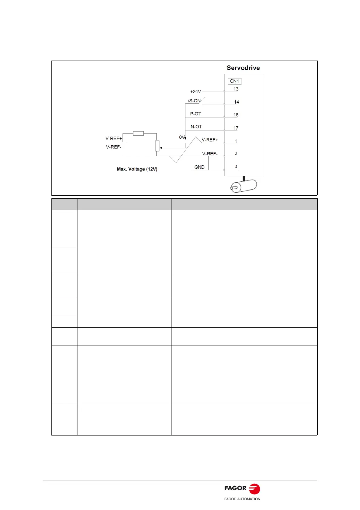
The following circuit is required: External input signal circuit or equivalent.
Step Description Check Method and Remarks
1
Check the power and input signal
circuits again, and check that the
speed reference input (voltage
between the V-REF+ and V-REF-) is
0 V.
Refer to the above figure for input signal circuit.
2
Turn ON the servo ON (/S-ON) input
signal.
If the servomotor rotates at extremely slow speed, refer to
4.4.3 Adjusting Reference Offset, and use the reference
voltage offset to keep the servomotor from moving.
3
Generally increase the speed
reference input voltage between V-
REF+ and V-REF- from 0 V.
The factory setting is 6 V/rated rotation speed.
4
Check the speed reference input to the
servodrive (Un001[rpm]).
Refer to 5.1.6 Operation in Monitor Mode.
5 Check the Un000 (motor speed [rpm]). Refer to 5.1.6 Operation in Monitor Mode.
6
Check that the Un001 and Un000
values in steps 4 and 5 are equal.
Change the speed reference input voltage and check that
Un001 and Un000 are equal for multiple speed references.
7
Check the speed reference input gain
and servomotor rotation direction.
Refer to the following equation to change the speed
reference input gain (Pn300).
Un001=(V-REF Voltage) [V] × Pn300
To change the servomotor rotation direction without
changing polarity for speed reference input voltage, refer to
4.3.2 Switching the Servomotor Rotation Direction.
Perform the operation from step 2 again after the servomotor
rotation direction is changed.
8
When the speed reference input is set
to 0 V and servo OFF status enters,
trial operation for servomotor without
load is completed.
 Loading...
