FaroArm
®
Manual
January 2009
31
Chapter 1: Introduction to the FaroArm
®
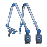
LEDs
The two LEDs, on the back of the Laser Line
Probe, indicate the distance to the target object
from the Laser Line Probe. Remember, data is
only sent to the computer when the Laser Line
Probe is in range.
• Out of Range (two Red LEDs). The Laser Line
Probe is too close or too far from the part.
• Center Range (two Green LEDs) The Laser
Line Probe is in the center of the range.
• Near Range (top Green LED only) The Laser
Line Probe is in range, closer to the part.
• Far Range (bottom Green LED only) The
Laser Line Probe is in range, farther from the
part.
Additionally, the software uses the R
ANGE
F
INDER dialog box to show the distance and
position from the Laser Line Probe to your part.
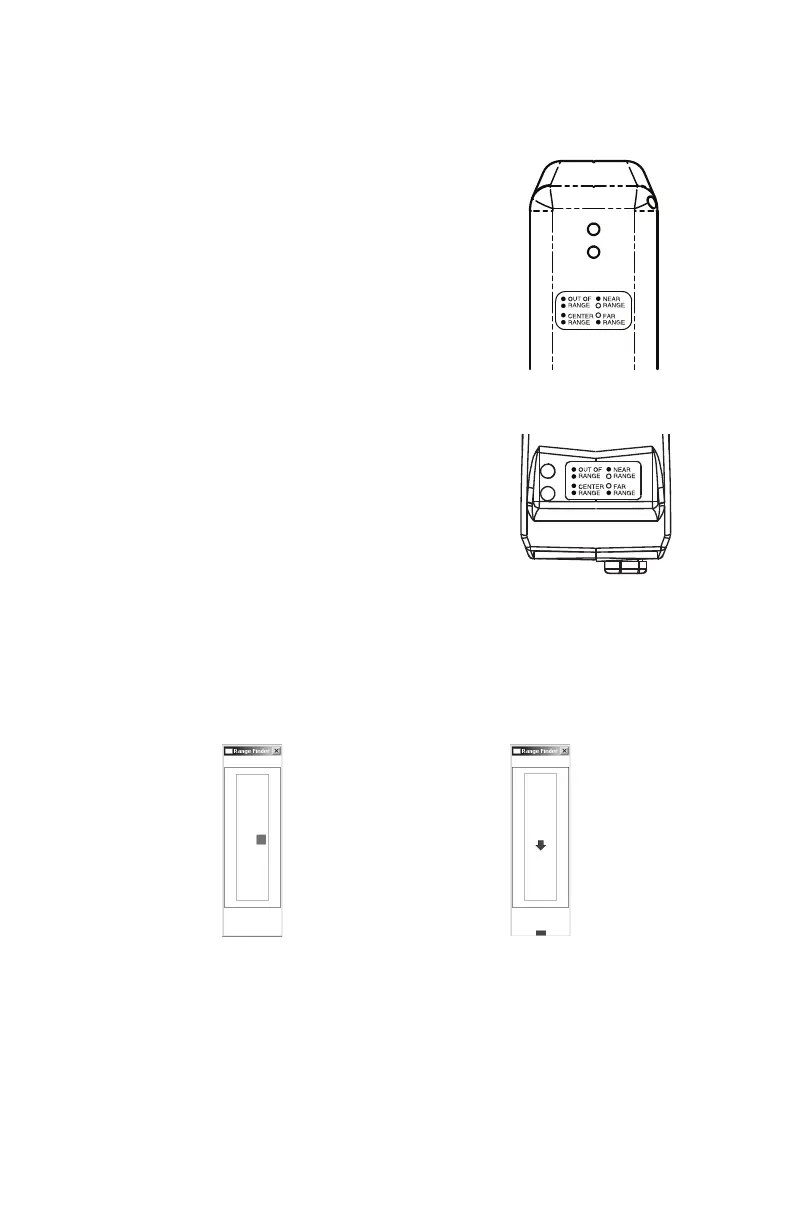
Range Finder
The FARO Laser Line Probe software has a R
ANGE FINDER dialog box.
This dialog box graphically displays the laser to part distance and the
area of the laser line that the camera is processing.
When the Laser Line Probe is within the operating range, the center of
the target displays as a small box in the R
ANGE FINDER dialog box, see
Figure 1-29.
The box moves as the Laser Line Probe moves:
• Up - as you move the Laser Line Probe closer to your part
Figure 1-29 Laser Line Probe in range Figure 1-30 Laser Line Probe not in range
08M46E00_FaroArmUSB.book Page 31 Tuesday, February 17, 2009 1:42 PM