67
OPERATION
17.3 Valve equipment
Text-module
Operation_Pic_number:1
Text-module
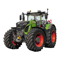
The four available hydraulic valves are identified
by the colours yellow, blue, red and green in all
the valve sub-menus, on the operating controls
and on the caps for front and rear connections.
● Yellow valve (standard) direction of actuation
(A).
● Blue valve (standard) direction of actuation
(B).
● Red valve (standard) toggle switch (C).
● Green valve (optional) toggle switch (D).
Fig.118
17.4 Operating the valves
NOTE:
After starting the tractor, the spool valves
must be unlocked (see OPERATION
Section 17.2).
Operation_Pic_number:1
Text-module
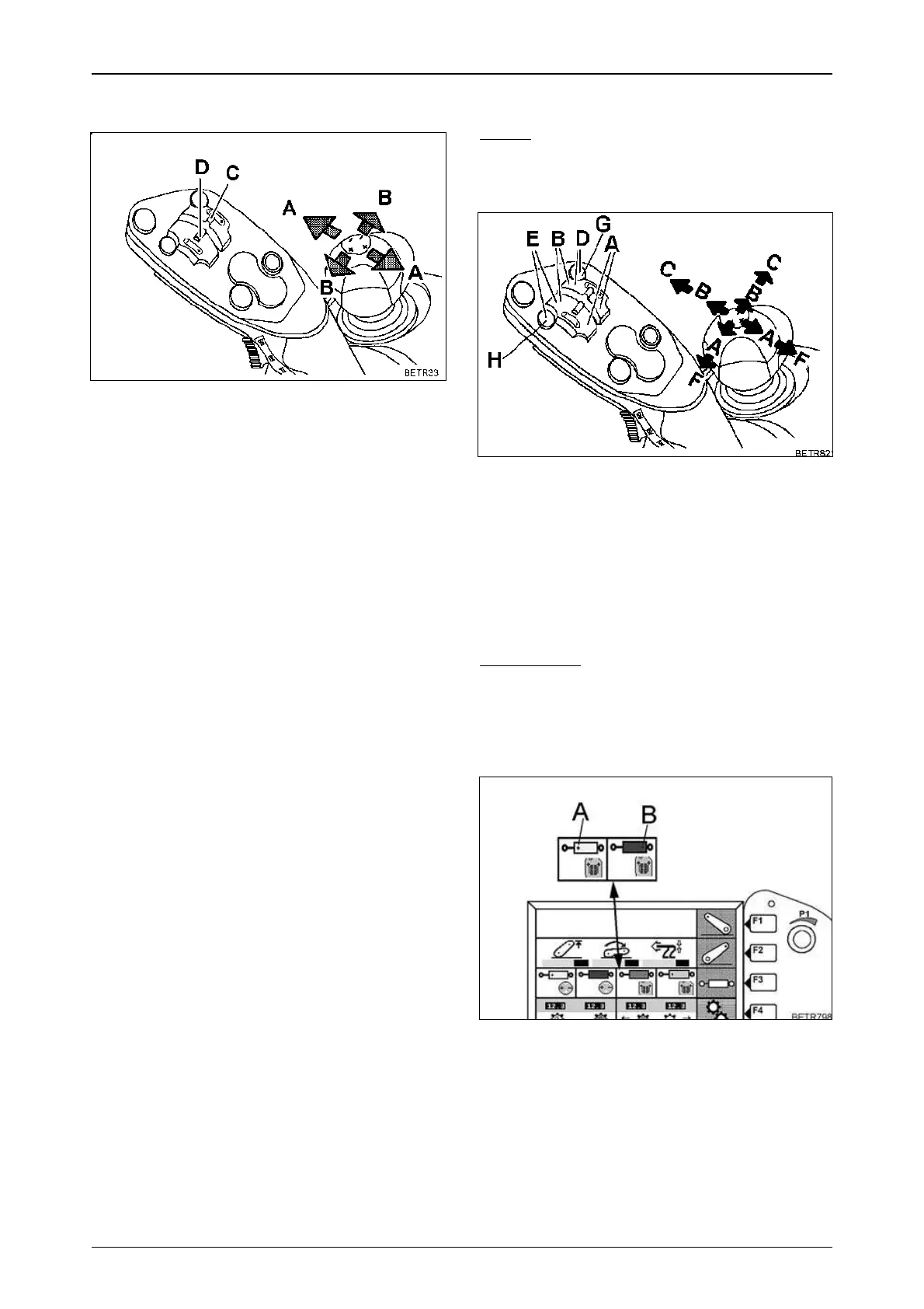
A = Raise
B = Lowering/pressure
C = Floating position yellow and blue valves
(red, green).
D or G = Floating position red valve (yellow).
E or H = Floating position green valve (blue).
F = No function.
IMPORTANT:
If the timer function is active, after the valve
is operated, it shuts off only after the preset
time has expired.
Valve actuation indicator
Operation_Pic_number:1
Symbols (A, B) appear whenever a valve is
actuated.
Fig.119
Fig.120
 Loading...