88
OPERATION
20. Front power lift
Text-module
(optional).
Text-module
If the 3.5 m distance of implement from steering
wheel is exceeded, take the appropriate steps to
ensure road safety (e.g. at road junctions, use
mirrors or an assistant to give hand signals). See
the country-specific vehicle licencing regulati-
ons.
Distance between lower links:
Category II = 825 mm.
IMPORTANT:
In order to keep the effect of the hydraulic ac-
cumulator, do not raise the implement to up-
per limit. (The load can bounce).
Text-module
Additional lighting
If the working lamps at the front are hidden by
the implement, switch on the additional lights.
The front headlamps will then go out.
20.1 Lower links
Swing compensation
Operation_Pic_number:1
Swing compensation for self-guiding
implements.
● Insert bolt (A) in hole as shown, and secure.
Text-module
DANGER:
Observe vehicle licencing
regulations, for example for
permitted axle loads, and the use of
counterweights.
For road haulage, observe the
maximum distance of 3.5 metres of
the implement from the centre of the
steering wheel.
When carrying extreme loads e.g.
cultivator, only thrust operation is
permitted.
Fig.195
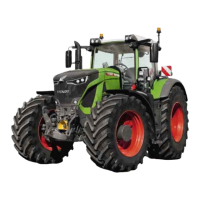
Removing the lower links
● Remove bolts (A, B).
NOTE:
If the lower links have been removed, use
bolts as the base for the lower links for better
assembly. Insert bolt (A) in lower hole.
Text-module
Lower link, parking position
NOTE:
Always fold up the lower links when not in
use.
Operation_Pic_number:1
● Insert bolt (A) in hole as shown and secure.
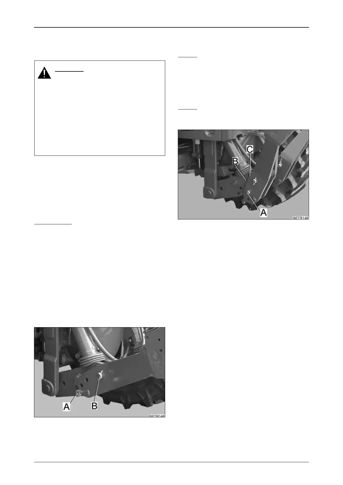
Text-module
The working range of the front lifting gear can be
modified by changing the lower guide point of
the lift cylinder.
Lifting cylinder in hole (B)
● larger lifting range of lower link.
Lifting cylinder in hole (C)
● higher lifting power.
Fig.196
 Loading...