94
OPERATION
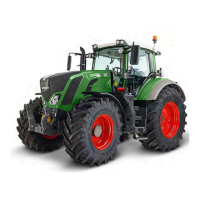
Floating position
Operation_Pic_number:1
● Quick Lift switch (P) at 'Control' (P1), LED is
lit.
● Move implement with depth control (O) to the
desired switch-on position.
● Quick Lift switch (P) at 'Raise' (P2), LED is lit.
Operation_Pic_number:1
● Quick Lift switch at 'Control' (P1) (does not
engage), LED is lit.
The power lift lowering movement is controlled,
floating position is selected only when the posi-
tion selected with the depth control is reached.
Symbol (E) appears.
Press button.
Fig.213
Fig.214
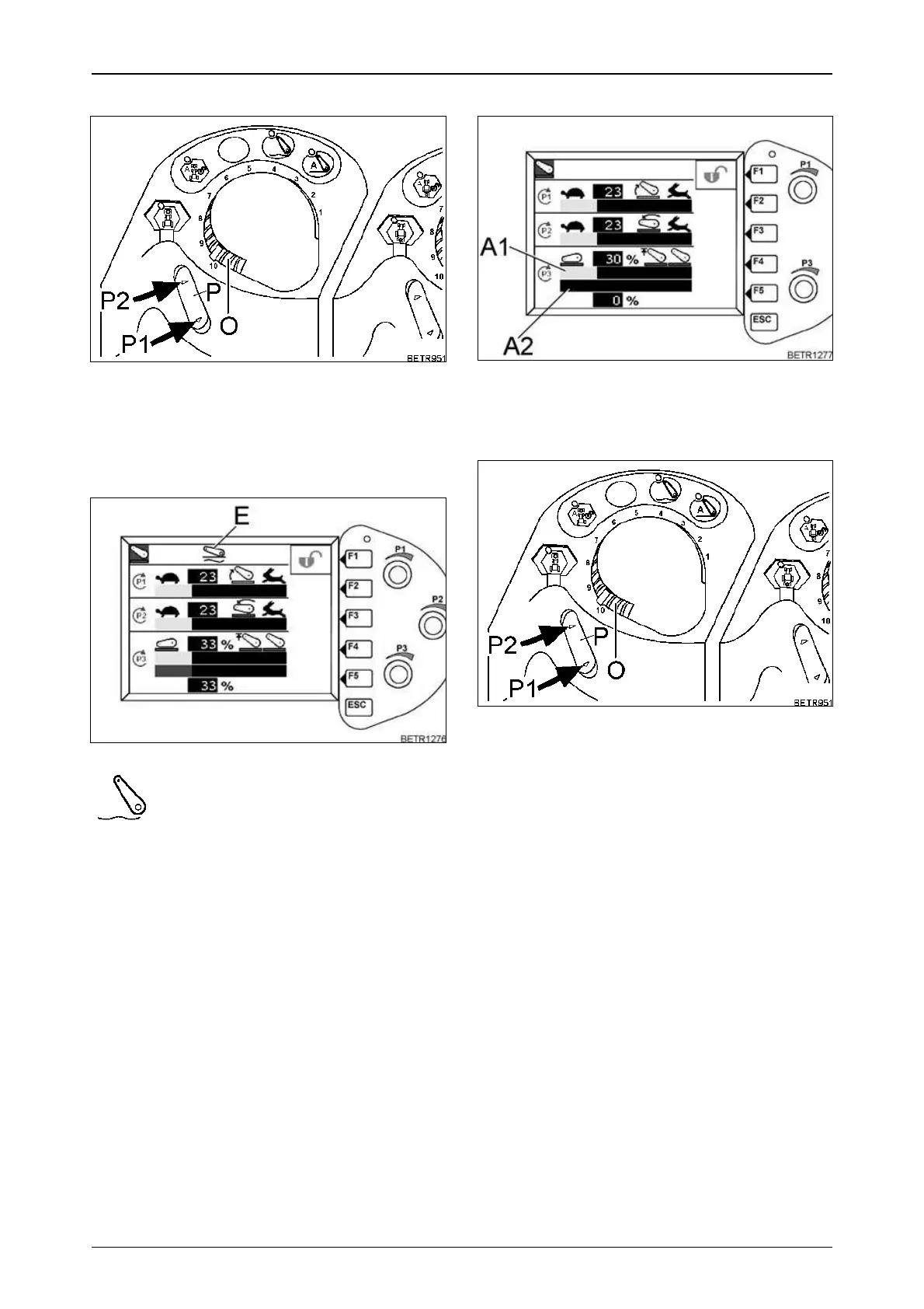
Hitching three-point implements
Operation_Pic_number:1
● With rotary switch (P3), set 30 % lift, bar indi-
cator (A1).
● Wait until indicator bar (A2) displays 0%.
Operation_Pic_number:1
● Quick Lift switch (P) at 'Control' (P1), LED is
lit.
● Lower the lifting arms by turning the depth
control (O) to the left. To raise the lifting arms,
turn the control to the right.
The upper and lower links are firmly attached to
the implement.
● Turn depth control (O) to '0' or quick lift switch
(P) to 'Lift' (P2) (no lock), LED lights up. The
implement is raised to the lift height limit (ap-
prox. 1/4 of the total lift height).
● Using rotary switch (P3), the implement can
now be raised to the desired height.
Fig.215
Fig.216
 Loading...