Note
The RUN/STOP rotary switch is set in the factory to position "1".
• Set the RUN/STOP rotary switch to position "0" (STOP) during installation to prevent the
program being started either automatically after the voltage is switched on or inadvertently by a
commissioning technician.
The RUN/STOP rotary switch must be accessible to be able to make settings:
• If necessary, remove the cover ( section Ensuring protection to IP65/IP67).
The position of the RUN/STOP rotary switch is forwarded to the controller by means of four internal digital
inputs and can be evaluated there.
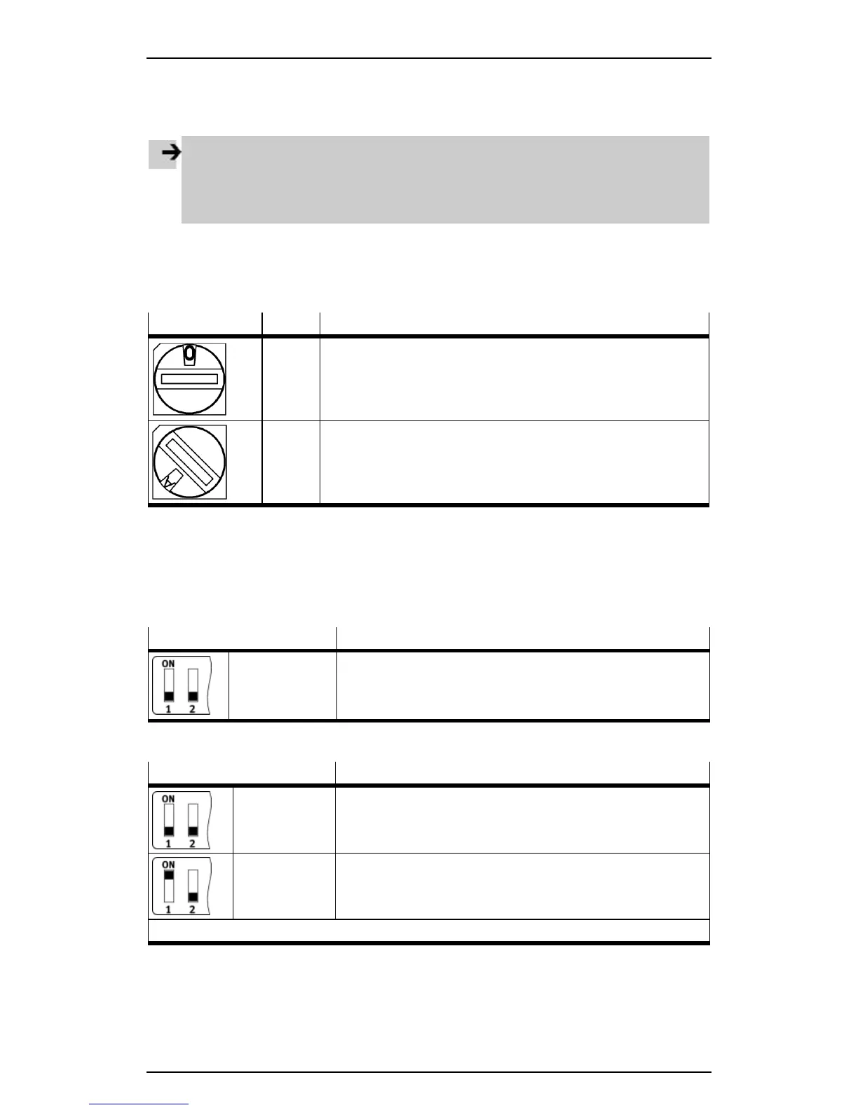
Switch position Setting Meaning
0 STOP
Codesys controller stopped. The STOP LED lights up yellow.
1 ... F RUN
Codesys controller started. The RUN LED lights up green.
Factory setting: 1
Table: Switch positions of the RUN/STOP rotary switch
3.4.2 DIL switches
The DIL switches must be accessible in order to make settings:
• If necessary, remove the cover or the IP65/IP67 plug from the Sub-D interface ( section Ensuring
protection to IP65/IP67).
DIL switch 1 Function
DIL 1.1: OFF
DIL 1.2: OFF
Reserved
• Leave the two switch elements of DIL switch 1 at OFF.
Table: Setting DIL switch 1
DIL switch 2 Function
DIL 1.1: OFF
DIL 1.2: OFF
CAN bus termination (120 Ω) switched off (factory setting).
DIL 2.1: ON
DIL 2.2: OFF
CAN bus termination (120 Ω) switched on (only with CPX-CEC-C1-
V3 and CPX-CEC-M1-V3).
All other switch positions are reserved.
Table: Setting DIL switch 2
DIL switch 2 is without function on the CPX-CEC-S1-V3.
13
 Loading...