Festo control block CPX-CEC
3.5.2 Communication interfaces
CANopen interface (CPX-CEC-C1-V3/-M1-V3)
The CPX-CEC-C1-V3/-M1-V3 provides a CANopen interface for connecting CAN bus slaves.
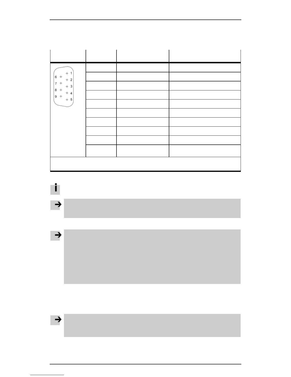
The CANopen interface is designed as a 9-pin Sub-D plug.
CAN bus plug Pin Signal Comment
1 n.c. Not connected
2
CAN_L
CAN Low
3
CAN_GND
CAN Ground
4 n.c. Not connected
5
CAN_SHLD
Connection to functional earth
6
CAN_GND
CAN Ground (optional)
7
CAN_H
CAN High
8 n.c. Not connected
9 n.c. Not connected
Housing (plug) The plug housing must be connected
to FE.
1) CAN Ground (optional), pin 6, on the CPX-CEC-C1-V3/-M1-V3 must not be used if a motor
controller with an external power supply is connected.
Table: Pin allocation of the CANopen interface (CPX-CEC-C1-V3/-M1-V3)
The CANopen interface does not supply the connected CAN bus slaves with voltage.
Note
• Use a protective cap or blanking plug to seal unused connections.
This provides protection to IP65/IP67 ( section Ensuring protection to IP65/IP67).
Connecting CANopen slaves
Note
If installation has not been carried out correctly and if high baud rates are used, data transmission
errors may occur as a result of signal reflections and attenuations.
Causes of transmission faults may be:
– Termination at DIL switch 2 set incorrectly ( section DIL switches)
– Incorrect screened connection
– Branches
– Long distances
– Unsuitable cables
• Use a twisted, screened 2-wire cable for the CANopen bus.
• Connect the housing of the CAN bus plug to FE via CAN_SHLD (pin 5).
In the case of motor controllers with external power supply:
• Make sure that CAN_GND (pin 6) on the CPX-CEC-...-V3 is not used.
Note
If the CPX terminal is fitted onto the moving part of a machine, the CAN bus cable on the moving
part must be provided with strain relief. Please observe also the relevant regulations in EN 60204
part 1.
15
 Loading...