Festo control block CPX-CEC
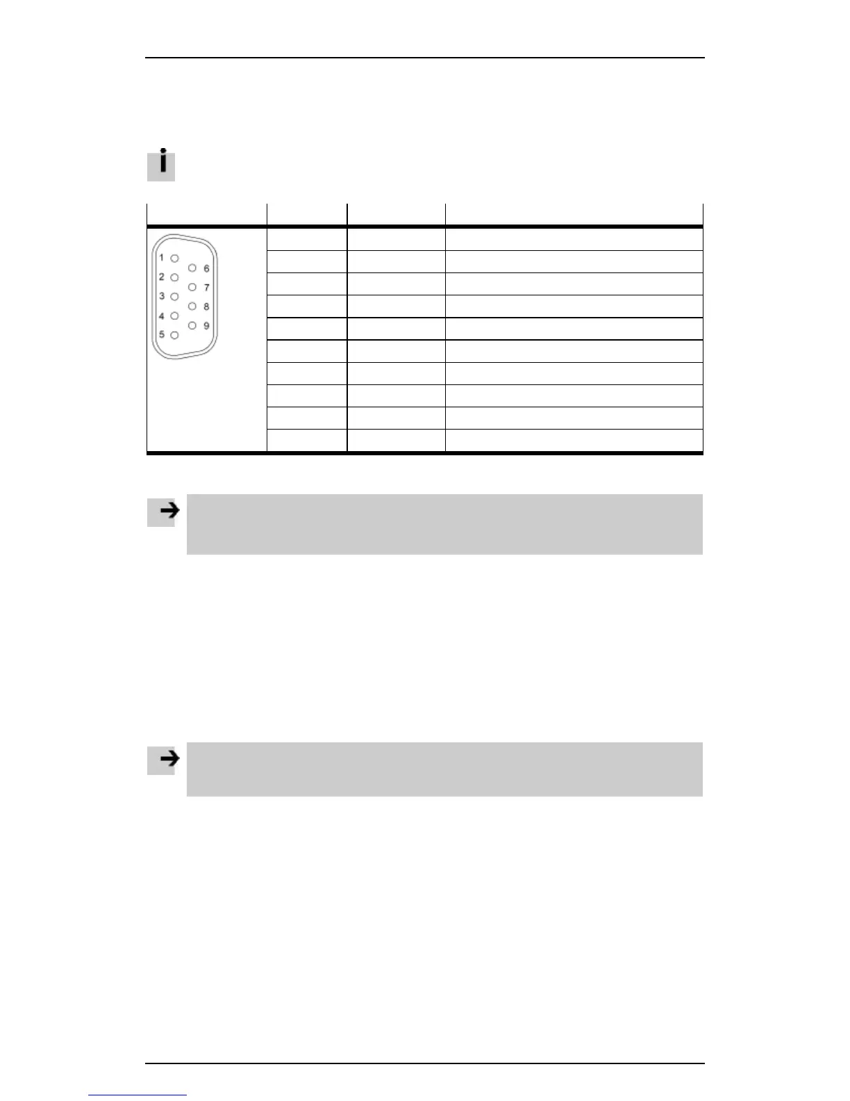
3.5.3 RS232 interface (CPX-CEC-S1-V3)
The RS232 interface enables external devices to be connected to the CPX-CEC-S1-V3.
When using external devices, data communication must be programmed by the user.
Socket Pin Signal Comment
1 n. c. Not connected
2
RxD Received data
3
TxD Transmitted data
4 n. c. Not connected
5
GND Data reference potential
6 n. c. Not connected
7 n. c. Not connected
8 n. c. Not connected
9 n. c. Not connected
Housing Screen Connection to functional earth
Table: Pin allocation of the RS232 interface (CPX-CEC-S1-V3)
Note
Long signal cables reduce interference immunity.
• Make sure that the signal cable is not longer than 30 m.
3.5.4 Power supply
The power for the device is supplied via the manifold sub-base.
– The device is supplied via the operating voltage supply for the electronics and sensors.
– The load voltage supply for valves and digital outputs is not required.
The device can therefore be combined with all manifold sub-bases.
– Manifold sub-base without supply
– Manifold sub-base with system supply
– Manifold sub-base with additional supply, if the module requires an additional supply to the right of the
CPX-CEC-...-V3 but there is not enough space for the additional supply.
Note
Further information on the power supply and the manifold sub-bases can be found in the CPX
system manual P.BE-CPX-SYS-...
17
 Loading...