Festo — EMCS-ST — 2021-03b
Display and operating components (HMI)
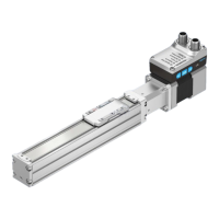
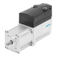
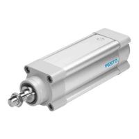
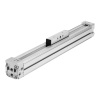
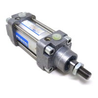
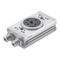
Electric cylinder unit Electric cylinder unit Rotary drive unit
EPCE-TB EPCS-BS ERMS
Tab. 5: Overview of electric cylinder and rotary drive units with integrated drive EMCS-ST
4.3
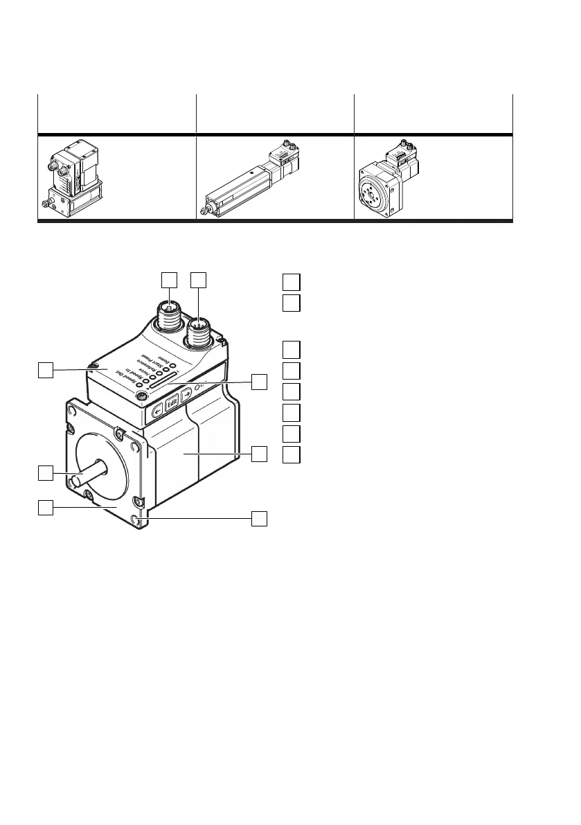
Product design
Fig. 3: Product design EMCS-ST (example EMCS-
ST-57 -...)
Connection for load voltage supply [Power]
Connection of logic power supply and dig-
ital inputs/outputs (DIO) or IO-Link (LK)
[Logic]
Display and operating components (HMI)
Stepper motor
Mounting holes
Motor flange
Motor shaft
Controller housing
5
Display and operating components (HMI)
5.1 Overview
The display and operating components (HMI) offer comprehensive options for parameterisation and
control of the integrated EMCS-ST drive.
Various LED displays are available on the controller housing for displaying parameter information,
motion status and menu selection.
Three pushbutton actuators are used to navigate through the menu or to control motions, e.g. to
perform a homing run.