Festo — EMCS-ST — 2021-03b
8.4 Connection variants
Damage to the device due to non-approved potentials at the pins
• Power connection:
• Do not connect pin 3
• Logic connection:
•
EMCS-ST is not hot-pluggable. Only after connection of the reference potentials GND/L– [Pin
4/8] can 24V levels be applied to digital outputs DO1/DO2 [Pin 2/3] or the IO-Link communi-
cation signal C/Q [Pin 3].
• The DO1/DO2 [Pin 2/3] digital outputs and the IO-Link C/Q [Pin 3] communication signal
must be disconnected 100 ms before the power supply connections GND/L– [Pin 4/8] and
24 V DC/L + [Pin 1], e.g. by the interposition of relay contacts.
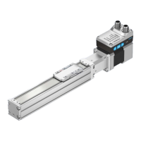
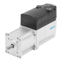
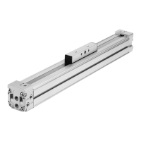
The connection of the integrated EMCS-ST drive depends on the "DIO operation" (digital inputs/
outputs) or "IO-Link operation" actuation mode and the connection cables (with or without adapter).
1.
Connect the cables to the [Logic] and [Power] connections of the integrated drive EMCS-ST.
2.
Connect cables to the controller or IO-Link master and to the PELV fixed power supply units.
8.4.1
Wiring diagram: DIO operation (digital I/O)
In NPN mode defined levels must be applied to the DI1/DI2 digital inputs of the EMCS, e.g. by
controller outputs with pull-up resistors (4.3 kW recommended).
The diagram shows the electrical connections of the integrated drive EMCS-ST to the load and logic
power supply and to the higher-level control (controller) in DIO mode.