Festo — EMCS-ST — 2021-03b
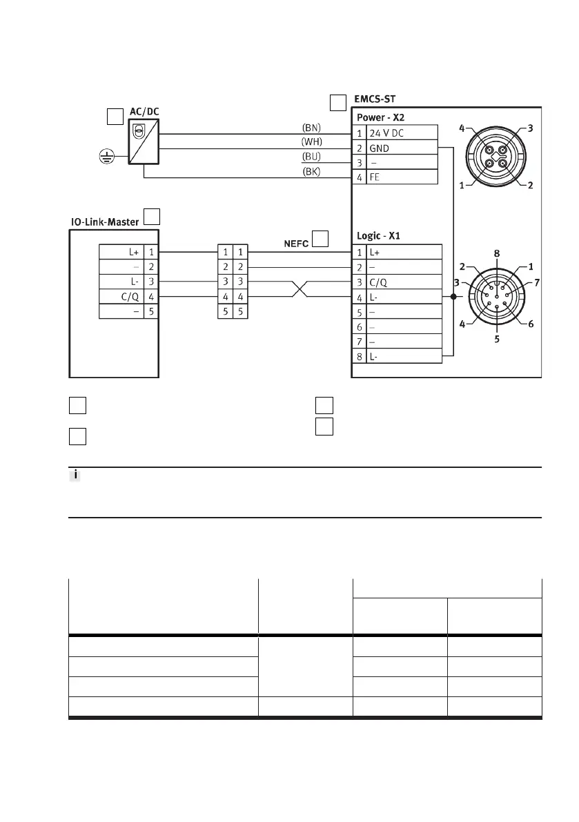
Fig. 8: Wiring diagram: IO-Link operation with adapter
PELV fixed power supply for load voltage
supply
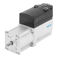
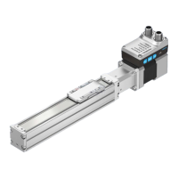
Integrated drive EMCS-ST
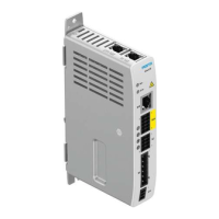
IO-Link master with IO-Link interface
Adapter NEFC
Core colours of Festo cables:
BK = black, BN = brown, BU = blue, GN = green, GY = grey, PK = pink, WH = white, YE = yellow
8.5
Electrical interfaces
All product variants of the integrated drive EMCS-ST support the following electrical interfaces
depending on the higher-level control interface:
Electrical interface Connection Control interface
Digital inputs/
outputs
IO-Link Master
Digital inputs/outputs (DIO) [Logic] yes –
IO-Link (LK) – yes
Logic voltage supply yes yes
Load voltage supply [Power] yes yes
Tab. 8: Overview of electrical interfaces
The electrical interfaces are located on the top of the controller housing.