Festo — EMCS-ST — 2021-03b
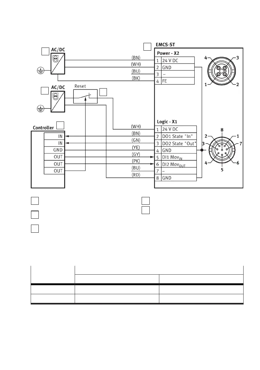
Fig. 6: Wiring diagram: DIO operation (digital I/O)
PELV fixed power supply for load voltage
supply
PELV fixed power supply for logic power
supply
Reset button for acknowledging an error
and triggering a restart (optional)
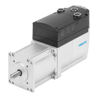
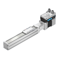
Integrated drive EMCS-ST
Higher-level controller with digital I/O
Status and control signals
The following table shows the status and control signals and the electrical levels of the digital inputs
and outputs as a function of the "PNP/NPN" version of the integrated drive.
Status and control
signal
Electrical levels
PNP, positive logic NPN, negative logic
0 Low level (0 V) High level (24 V)
1 High level (24 V) Low level (0 V)
Tab. 7: Overview of status and control signals as a function of electrical levels
8.4.2
Wiring diagram: IO-Link operation, port class A (with and without NEFC adapter)
The diagram shows the electrical connections of the integrated EMCS-ST drive to the load voltage
supply and to the higher-level IO-Link master in IO-Link operation.