Festo — EMCS-ST — 2021-03b
[Logic]
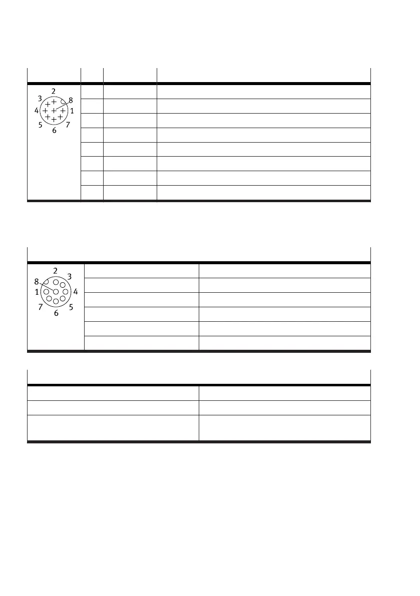
1)
Pin Function Description
1 L+ IO-Link power supply (24 V DC)
2 – reserved, do not connect
3 C/Q Communication to the IO-Link Master
4 L– Reference potential IO-Link power supply (0 V)
2)
5 – reserved, do not connect
6 – reserved, do not connect
7 – reserved, do not connect
8 L– Reference potential IO-Link Power supply (0 V)
2)
1) plug M12x1, A-coded, 8-pin
2) Pins 4, 8 [Logic] and pin 2 [Power] are internally connected.
Tab. 10: Connection [Logic]: IO-Link (LK)
Requirements for plug and cable
Mating plug requirements
Design Socket M12x1, A-coded
Number of pins 8
Nominal current 2 A
Rated voltage 30 V DC
Degree of protection IP65
Shielding No
Tab. 11: Mating plug requirements
Requirements for the connecting cable
Number of insulated wires and shielding 8 insulated wires, unshielded
Min. cable cross section 0.25 mm
2
Max. cable length 30 m (DIO mode)
20 m (IO-Link operation)
Tab. 12: Requirements for the connecting cable (single device)
8.5.3 Connection [Power]: load voltage supply
The power unit of the electronics is supplied with voltage via the [Power] connection.